Camera Pixel Reconstructor
Basically Doing it In Reverse
Please Log In for full access to the web site.
Note that this link will take you to an external site (https://shimmer.mit.edu) to authenticate, and then you will be redirected back to this page.
Enter: OV5640
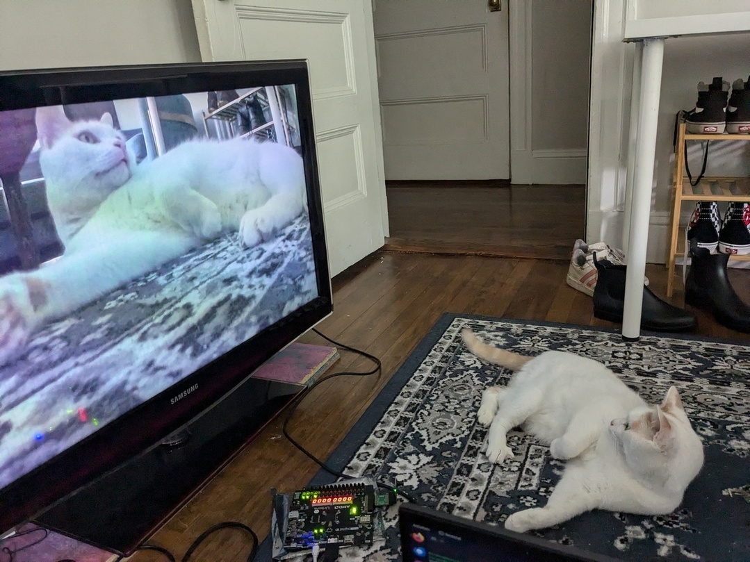
I want to use my FPGA to look at a cat. A live, real-time cat! You know what you need in order to to look at a cat in real-time? A cat A camera!

Later in this week's lab, you'll use the OV5640 camera sensor and get its camera data to display on the HDMI output you constructed last week. Its datasheet is available here, and there's a lot of really interesting stuff to learn from it and the different settings you can configure for it. But for the purposes of this lab, we'll take care of all the settings configuration for you, so that the data can be easily accessible to you. Your job in this exercise is to write logic to interpret the data that comes in from the camera as a full image.
The format the camera will use to send us sensor data (referred to by the datasheet as "Digital Video Port") bears similarity to the way we send data over HDMI to our monitors. Just like with our HDMI transmitter, the camera sends us pixels left-to-right, top-to-bottom. It uses hsync and vsync signals to indicate the start of new rows and the start of new frames. However, unlike HDMI, it sends its data frames in parallel: there are 8 parallel wires which each carry part of an 8-bit message simultaneously, rather than having to serialize the data onto one wire.
But wait! 8 bits isn't enough to send a full-color pixel! Specifically, the OV5640 will be set to give us 16-bit color, using the RGB565 format1. In order to handle this, it'll be our responsibility to properly stitch two adjacent sets of 8 bits together and make a full pixel.
Your job is to design a pixel_reconstructor module, that takes the input data wires from the camera and outputs a single-cycle-high valid signal for each new pixel, alongside its coordinate location within the image.
input wire camera_pclk_in: The data clock provided by the camera: the transition from0to1on this wire defines the time when all other camera data wires should be read.2input wire camera_hs_in: Horizontal sync (active low): when this signal is low, a row of pixels has completed and the camera is about to send the next row of pixels.input wire camera_vs_in: Vertical sync (active low): when this signal is low, a full frame of pixels has been sent and the camera is about to start to send the next frame, beginning in the top left corner.input wire [7:0] camera_data_in: The 8 parallel wires transmitting pixel data, one byte at a time. Each pixel is 16 bits wide and is sent on 2 sequential cycles ofpclk: first the upper 8 bits are sent, then the lower 8 bits are sent. When bothhsandvsare high, the bytes captured on these wires are valid data; otherwise, we're in a blanking period andcamera_datashould be ignored.
Based on the camera inputs, you should generate the following set of outputs:
output logic pixel_valid_out: Single-cycle high when a full pixel's data has been captured.output logic [HCOUNT_WIDTH-1:0] pixel_hcount_out: The horizontal coordinate you've determined for the pixel being transmitted.output logic [VCOUNT_WIDTH-1:0] pixel_vcount_out: The vertical coordinate you've determined for the pixel being transmitted.output logic [15:0] pixel_data_out: the reconstructed 16-bit pixel value.
The Camera's Video Protocol
The protocol through which the camera provides us data is pretty approachable, and primarily simply relies on reading data when we see PCLK transition from 0 to 1, just like we did when receiving data over SPI. A handful of notes about the protocol:
- The pixel data we receive is valid when both
hsyncandvsyncare high. Note the polarity of this; a0on a sync wire indicates a syncing region. Additionally, note that there is no front porch/back porch the way we've had in the past; the data is always either in a sync state or its giving us valid data. - When
hsynchas a transition from1to0, we know that a row has completed and we should start interpreting future valid data as the next row, starting again from the left side. - When
vsyncis low, we know that a frame has completed and we should start interpreting future data as starting from the top left corner. Note that whilevsyncis low, we should ignore any falling edge ofhsync! Any change in thehsyncvalue during thevsyncregion doesn't hold any meaning for us. - Pixels come with their upper 8 bits first. Make sure you stitch things together the right way around.
Hints and Suggestions as you write:
- We've often found ourselves creating
_prevregisters that allow us to track transition points of signals, and these will definitely come in use here. For sampling the data wires from the camera though, you don't necessarily want to keep track of transitions that happen within eachsys_clkcycle, since we only know the data to be valid whenPCLKtransitions from0to1. So, it could be helpful to keep a register likelast_sample_hsyncthat stores the previous value seen at a valid sample point.- Also, if you keep track of the
[7:0] last_sample_data, then you'll have access to the last 8 bits and the present 8 bits (a.k.a. a full 16 bit pixel) when you receive the second half. - As a blanket rule, don't assume any signal from the camera is valid unless you detect a valid sample point from
PCLK.
- Also, if you keep track of the
- Consider tracking a
half_pixel_readysignal that alternates as new 8-bit samples come in during an active region, so you know when a pixel has been completed. You only have a new valid pixel on every other sample point from the camera data bus, so you only want to actually assertpixel_valid_outwhenhalf_pixel_readyis high. Ensure this signal resets whenever you're in a syncing region, so you don't accidentally stitch together bytes at the edges of two rows! Or, approach this with an FSM!- Think through where the transitions for this flag should happen, so that you don't get off by 1 byte and interpret two halves of adjacent pixels as part of the same pixel! And test locally/look at waveforms to make sure you're not prematurely sending out
pixel_valid_outsignals.
- Think through where the transitions for this flag should happen, so that you don't get off by 1 byte and interpret two halves of adjacent pixels as part of the same pixel! And test locally/look at waveforms to make sure you're not prematurely sending out
Testing your pixel receiver
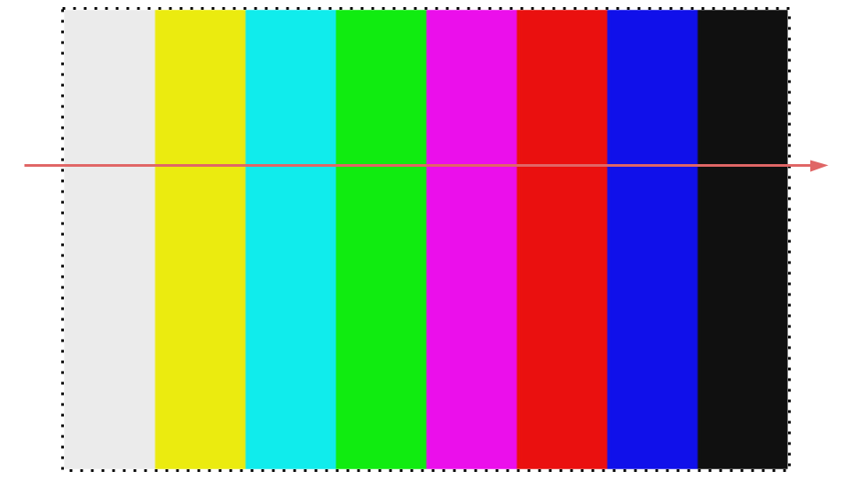
As usual, testbenching is beautiful and lovely and will make your life happy. With all the data it's trying to spit at you, trying to debug your interpretation of camera signals in hardware will make your life sad. So, make a testbench! Here, we've attached a waveform that is actually captured from hardware, showing one row of what the camera spit out when it was configured to transmit a color-bars test pattern.

As you create your testbench, it would be a good idea to drive your camera signals to resemble what you see in that waveform. Perhaps send in fewer than 1280 pixels per row, and test multiple rows and multiple frames. Make sure that you test and ensure that you're successfully outputting pixels with the proper high byte and the proper low byte, and not accidentally stitching together halves of two adjacent pixels! Once you've tested your pixel reconstructor, submit it below.
Submit your tested pixel reconstruction module here!
No file selected
Once you're done, feel free to move on to making PopCat Pop :D.
Footnotes
1Just like the 16 switches we set to choose a color back in week 1!
2This clock will be slow enough that we can reliably sample during every half-period of the clock, so we can always measure the transition from 0 to 1. In order to accomplish this, we'll have to work with a faster FPGA clock, as you'll see when we take this to hardware
3The edges of each color bar are a bit blurry in the camera's output; don't worry too much about that!