Please Log In for full access to the web site.
Note that this link will take you to an external site (https://shimmer.mit.edu) to authenticate, and then you will be redirected back to this page.
In this lab, we’ll be attaching cameras to our FPGA so that when we dangle a little piece of pink plastic in front of it, we can detect its position. We’ll use this position to set the location of an image sprite, which we’ll be able to move around on a monitor by moving the pink plastic in real life. Here’s a quick demo of what this'll look like at the end:
Thus far we've only been giving input to our FPGA with switches and buttons - and for good reason! Using them is only as complicated as the debouncing logic, but as we make more complicated systems we'll want more natural ways of interacting with them. This kind of object detection is a jaunt in this direction - it's not hard to imagine using this technique to make a game controlled by gestures, or the locations of other objects in the real world. 1 Many fantastic final projects for this class have used this method!
Going from the raw camera pixels to controlling popcat with pink mailer will require:
- Reading frames from a super cheap VGA camera. We've done most of this for you, but you'll still need to understand how this works.
- Splitting these frames into their RGB and YCrCb components.
- Selecting pixels from the frame based on their values in a particular channel.
- Finding the centroid of our selected pixels using a center of mass method.
- Outputting an image sprite at the coordinates of the centroid.
- Adjusting the overall system pipeline so that latency is consistent across all data paths.
All of these steps stack up to a linear image processing pipeline that's conceptually pretty simple, but has a very nuanced implementataion! Only a handful of the operations we'll perform will be possible with purely combinational logic - we'll need a fair bit of sequential logic, which will add delay to our pipeline. Properly compensating for these delays as we implement our pipeline is the focus of this lab.
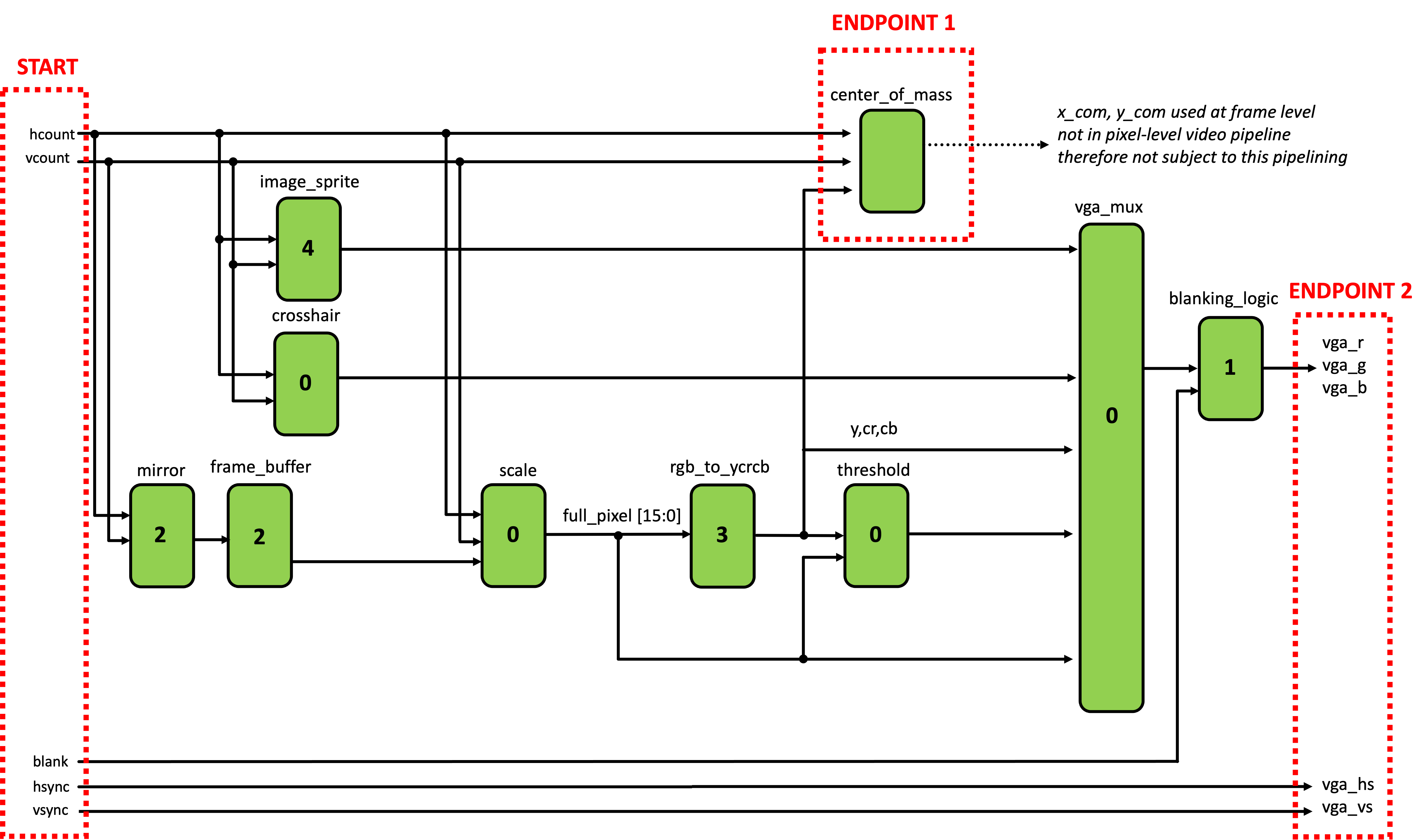
Let’s have a look at what our system will look like.
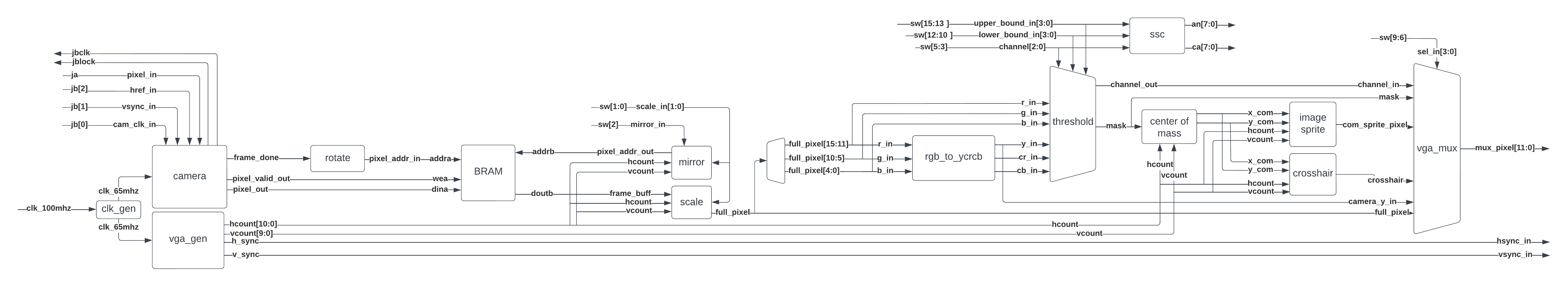
Information flows in the schematic from left to right, which shows a few of the steps mentioned previously, as well as a LOT of intermediary steps. Let’s walk through what exactly is happening in each module:
clk_wizis reused from lab03, and again generates a 65MHz clock from the 100MHz clock. We’ll be using this for two purposes:- Supplying the pixel clock for the VGA output of our boards, just like it did in lab03
- Supplying a derived pixel clock for the camera (at 65\div 4 \approx 16.6 \text{MHz}). The OV7670 cameras on our camera boards output video as VGA, but require us to supply a pixel clock. This clock is used by the camera’s internal logic, and then returned to the FPGA a reference clock.
vga_genis also reused from lab03, and it produces the signals needed for the FPGA’s VGA output.camerareads the signals from the camera board, and outputs pixels onpixel_data_outaccordingly. It’s also got apixel_valid_outoutput that signals when there's new, valid pixels onpixel_data_out. Theframe_doneoutput also signals when a new frame has been read in.
{R, G, B} color format as we saw in lab03. Instead it uses a 16-bit color scheme called RGB565, where 5 bits are given for the red channel, 6 for the green, and 5 for the blue. This means our camera input is 16-bits wide, so we'll have to take the top four bits of each channel when we output to the display. We'll only do this right before we write to the display, as we don't want to throw away any bits until we absolutely need to. 2-
Next, we read the camera's pixel values into a framebuffer. The camera's output resolution and framerate doesn't match that of our 1024x768 VGA display, so we buffer the camera's output while we wait for it to give us frames. This also lets us conventiently solve two other problems:
-
Image rotation - the camera outputs video sideways, and we correct for this by rotating it back. This is done by choosing the addresses that we write pixels to such that the image is rotated as it's placed in the framebuffer.
-
Clock domain crossing - the camera pixels are still in the camera’s
cam_clkclock domain, so we need to move those into theclk_65mhzdomain to match the rest of our logic downstream. We could do this with a buffer just like we would for any other clock-domain crossing, but we needed this big BRAM anyway, so let’s just use that.
-
-
Once we’ve got our image in the framebuffer, we'll want to read it out and send it down the rest of the pipeline. However the image from our camera is 640x480, which isn't very large on our 1024x768 monitors, so we'll scale it up with the
transformmodule. We'll also add a mirroring ability on this module, which will cause our objects to show up in their intuitive locations on the screen. You'll be implementing this module. -
From there, our rotate, scaled, mirrored, and properly clocked camera pixel goes to
rgb_to_ycrcb.sv, which converts it from RGB to YCrCb color space. -
We then take all of our color components from each color space - R, G, B, Y, Cr, Cb - and route them to the
thresholdmodule. This lets us choose a channel to select pixels from, as well as an upper and lower bound for their values. From this we're able to produce a 'mask' - a bit for every pixel that's 1 if it lies within the bounds we set, and zero if not. -
The color channel and bounds we choose are also displayed on the 7-segment display with the
sscmodule. The output is formatted like {upper bound, color channel, lower bound}, so a value of111Cr001on the display means that only with a red chrominance between3b111and3b001are being used. -
The centroid of the object is then estimated by the
center_of_massmodule, which you'll implement. It works by calculating the average position of every pixel in the mask, and using that as the mask's centroid. 3 You'll implement this module a bit later. -
The x, y coordinates of the centroid are passed to an
image_sprite, which is drawn with its center at the mask's centroid. A crosshair that tracks the centroid is also drawn from the same coordinates. -
The mask, image sprite, crosshair, and mask are all fed to
vga_mux, which determines what's shown on the display. The full-color camera output is also fed to the module so you can check the image input to the pipeline. We've also routed the Y-channel (greyscale) camera output to the mux so you can see the mask/crosshair/image sprite over a greyed-out frame.
There's a lot of steps in this pipeline! Take some time to get comfy with it. We've provided most of the boilerplate, but you'll be implementing the transform and center_of_mass modules.
The onboard switches control the image pipeline and have the following meanings, which are also shown on your cardboard reference card.
sw[1:0]controls the scale of the image, where00scales the image by a factor of 101scales the image by a factor of 210and11scale the image by a factor of 8/3.
sw[2]produces a mirrored imagesw[5:3]controls the color channel used to produce our mask, where:000selects the red channel001selects the green channel010selects the blue channel011just outputs zeros100selects the Y channel101selects the Cr channel110selects the Cb channel111just outputs zeros
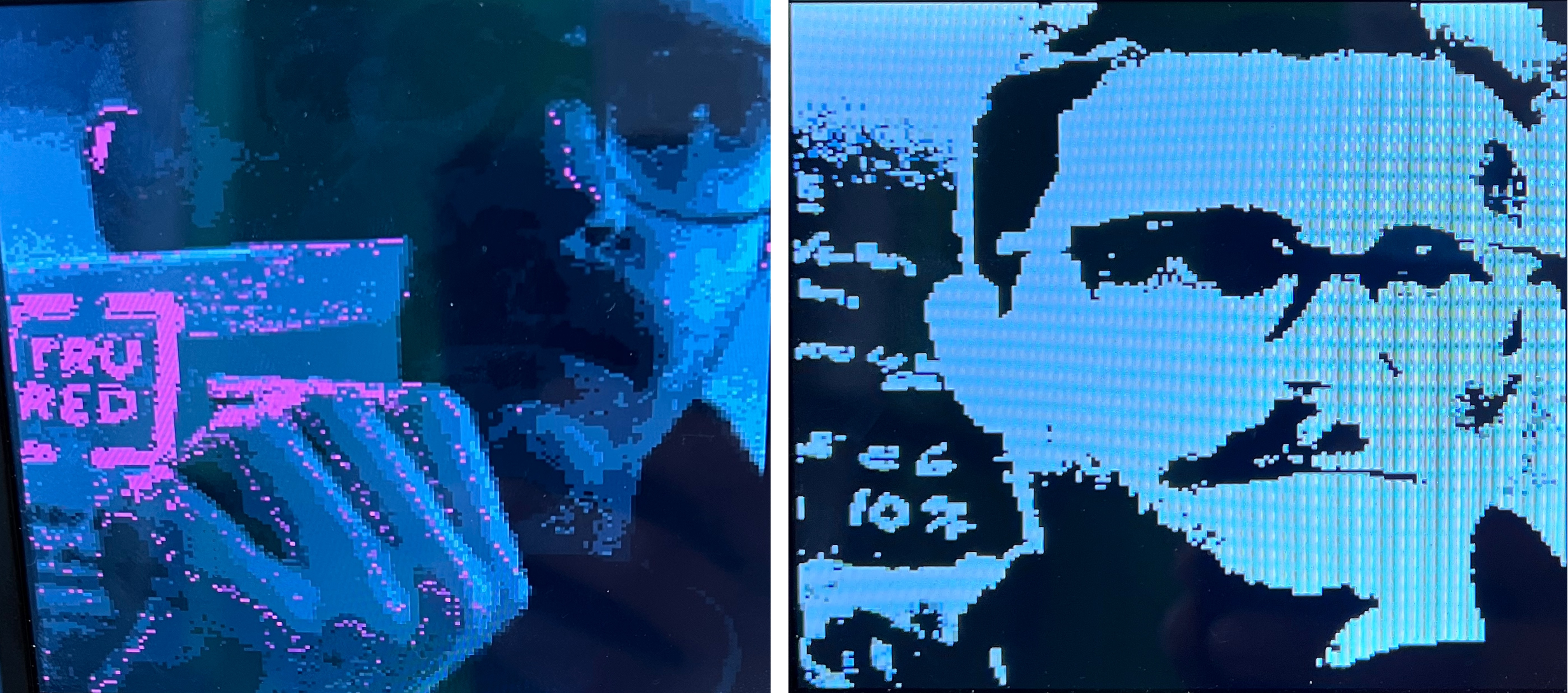
sw[7:6]controls how the color mask is displayed, where:00selects the raw camera output01selects the color channel being used to produce the mask. For example, if the blue channel was selected withsw[5:3]=010, then we'd output the 12-bit color{b, b, b}to the screen.10displays the mask itself11turns the mask pink, and overlays it against a greyscale'd camera output.
sw[9:8]controls what's done with the CoM information:00nothing01crosshair10sprite on top11magneta blob for testing
sw[12:10]set the lower bound on the pixel channel that generates the mask.sw[15:13]set the upper bound on the color channel that generates the mask.
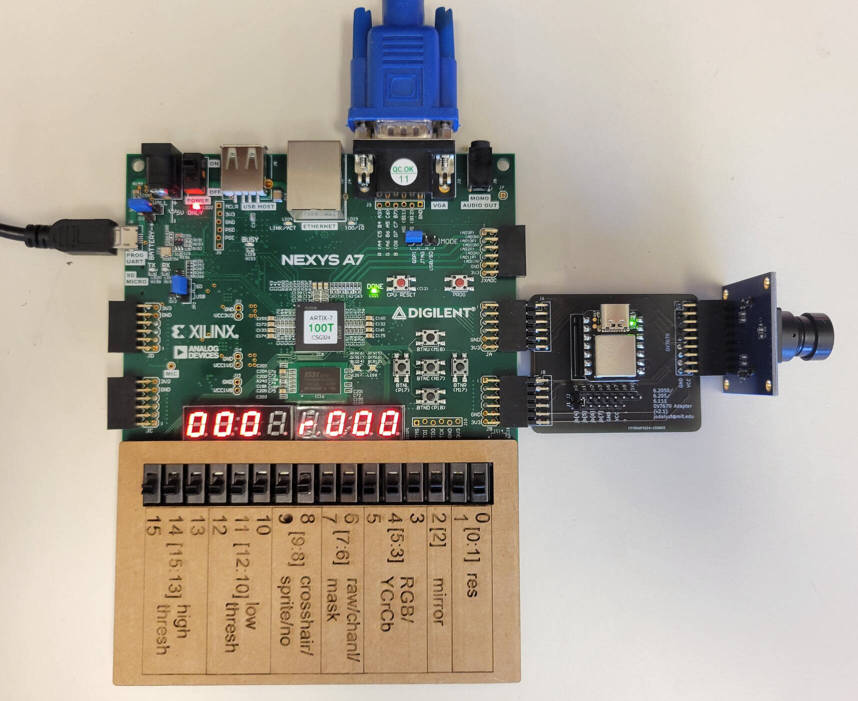
Before you get started, run to the front of lab and grab:
- A camera board, and plug it into the two PMOD ports4 labelled JA and JB on your board. Make sure you don't have the lens cap on.
- A cardboard cutout to put over the switch labels, just to make remembering their functions easier.
- A pink mailer (bubble wrap evelope), which we'll be using as our target.
- Either a VGA monitor, or an HDMI monitor with a VGA-HDMI adapter just like in lab03. If you’ve got the choice between the two, we recommend the former since the adapters can be finnicky.
- The starter code from our GitHub.
Your setup should look like this once you have everything. With only sw[9:8] set to 11 and all switches set to zero you should see a pink screen on your monitor. With all the switches set to zero, nothing will appear on the monitor until you complete scale, at which point the output from your camera will show on the monitor! Use that to set the focus of the camera by rotating the lens.
The frames we write into our framebuffer BRAM are 240x320, and are being updated at around 20-30 frames per second. As you've probably noticed by now, this doesn't look very big on our 1024x768 monitors! We'd like to enlarge it so that it's easier to see what's going on. We'd like to be able to scale our camera output by a factor of 1, 2, or 8/3 (this results in a 640x853 image, where makes the x dimension a clean multiple of 240). We'll be doing this by making it such that multiple pixels in the output obtain their color values from a single pixel - which we can do by addressing the BRAM intelligently.
With that out of the way, let's turn to actually implementing the scale module. Here are the inputs and outputs the module will need:
scale_in: an input that specifies the scale factor of the image, where:2'b00: corresponds to 1X scaling, and produces a 240x320 image2'b01: corresponds to 2X scaling, and produces a 480x640 image2'b10: corresponds to 8/3X scaling, and produces a 640x853 image2'b11: Is undefined and the behavior is up to you.
hcount_in [10:0]: the horizontal location of the current pixel in the imagevcount_in [9:0]: vertical location of the current pixel in the imageframe_buff_in [15:0]: the pixels we get back from the BRAM, encoded as RGB565.cam_out [15:0]: the output from the module, encoded as RGB565.
This module is relatively simple and should be implemented with combinational only logic. The actual looking up of the appropriate pixel is accomplished by the mirror module we've provided, which computes an address based on the values of mirror_in and scale_in. In the scale module you're about to write, you must choose to display either the pixel from the framebuffer (frame_buff_in) or a black pixel (16h0000), given the current pixel location (hcount and vcount).
We've included a testbench for you to play this in sim/scale_tb.sv, which is the exact same testbench as in the CATSOOP question below - only difference is that CATSOOP will automatically compare our implementation to yours. Getting 100% on this question isn't required for the lab (only the checkoffs are) but this is for your convenience to make sure that you're producing the right result.
As usual, playing with things here is going to be far easier than doing any testing in hardware, so get your module working in sim first. When this module is working, place it into your project and build it on hardware. Once it's working, move onto the next section.

Now that we've got an image that's large enough to work with, we can move onto the masking step in our image pipeline. We've provided the Verilog to produce the mask based on the values in the selected color channel - that's all in the threshold module. Your job here is to mess with the switches to see what can and can't be well filtered and tracked with your system, starting with the pink mailer you grabbed at the beginning of the lab.
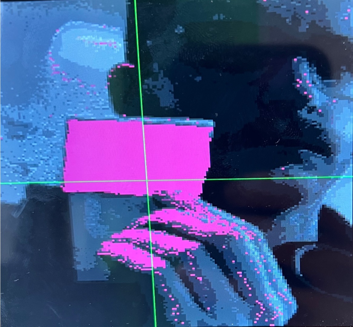
Tweaking the switches gives you sufficient flexibility to see pretty much anything in the video processing pipeline, feel free to check either your cardboard or the [Switch Reference](#Switch Reference) if you need a refresher on what each one does. Setting sw[7:6] = 2'b11 is particularly useful as it draws the mask in pink, while leaving everything that's unmasked in greyscale. The greyscale here is taken from the luminance of the camera image, which is the Y channel is YCrCb space.
The seven segment LEDs will display your current upper and lower thresholds (in binary) as well as your color channel selection (r,g,b,y,Cr, or Cb). Using this in combination with the video out on the screen should guide your intuition towards the mask generation here. Start by trying to detect the pink mailer, and then move on to other kinds of objects. Find another object that's reasonably well detected by thresholding on one particular channel. See what works and what doesn't.
Demonstrate your working scale module in hardware. We'll want to see the image size change based on the values of sw[1:0]. Also be prepared to explain to us how the masking works. Show us how to track the pink mailer, and another object of your choice. If you run across anything else interesting, show us that too!
Now that we've generated our mask, we'll want to find it's approximate center, or centroid. We'll compute this once per frame, and it'll work by taking the center of mass (CoM) of the mask.
...wait, physics? In my digital design class?
Yep! Just like we can compute the CoM for any object in the real world, we can compute the CoM of our mask. And just like how in real life the CoM of an object is approximately at its center, the CoM of our mask will be at approximately at the center of our mask. And since our object is being selected out of the scene by our mask, the mask's CoM should be pretty close to the center of the object we're tracking.
We can think of our mask as a collection of pixels that all have some 'mass', and are all connected together. Back in 8.01 we had a formula for finding the center of mass (x_{CoM}, y_{CoM}):
m_{total} = \sum_{n} m_n
x_{CoM} = \frac{\sum_{n} m_n * x_n}{m_{total}}
y_{CoM} = \frac{\sum_{n} m_n * y_n}{m_{total}}
Where m_{total} is the total mass of our object, calculated as the sum of masses of all the smaller objects that comprise it. x_{CoM} and y_{CoM} are then computed by taking the weighted average of each mass in the object, and then dividing by the total mass of the object.
This works for physical objects in the real world, but since our mask can only be one or zero (it either lies within the thresholds we've set, or not), we can treat every pixel as having the same mass, which reduces the formula to:
m_{total}= \sum_{n} 1
x_{CoM} = \frac{\sum_{n} x_n}{m_{total}}
y_{CoM} = \frac{\sum_{n} y_n}{m_{total}}
If you notice, this has actually just reduced to taking the average position of each pixel's x and y coordinate! This is super simple, and is suffecient to estimate the center of our object.
Let's turn to implementing this in Verilog. We've given you a skeletonized verion of it in src/ that you'll fill out with the proper logic. This module has the following inputs:
clk_in: system clock, in this case the 65MHz pixel clockrst_in: system reset[10:0] x_in: horizontal position of the current pixel being provided to the module[9:0] y_in: vertical position of the current pixel being provided to the modulevalid_in: indicates a valid (x,y) or (horizontal, vertical) point to be added.tabulate_in: Used to trigger the final calculation of the average horizontal and vertical pixel position (will be a single-cycle assert)
And the following outputs:
[10:0] x_out: Calculated average 11 bit horizontal position[9:0] y_out: Calculated average 10 bit vertical positionvalid_out: Indicates a valid (x,y) or (horizontal, vertical) point has been produced.
The module should work by taking the average of all "valid" pixels on a frame-by-frame basis. It should do this by summing the x and y locations of every valid pixel (indicated by the valid_in signal); along with this it should tally how many pixels are recorded. When tabulate_in is triggered, the system should enter a dividing state where it uses the total sum of x positions along with the total number of pixels tallied to calculate an average x position for all valid pixels; similarly it should do this for the y dimension as well. We have provided a 32 bit variant of the adder from Lecture 06 that you can use with this module (called divider.sv in the lab starter code). The latency of the divider module is variable, depending on what is being divided, so you will need to build your center of mass FSM to account for this. Review Lecture 07 for discussion on the major/minor FSM abstraction. When the average has been calculated for BOTH dimensions, your center_of_mass module should make sure to have those two values on the x_out and y_out outputs and indicate their validity via a single-cycle assertion of valid_out. Downstream logic will be looking for this and will update the x_com and y_com variables in top_level appropriately.
Your job is to not only write the center_of_mass module to spec, but also to verify it with a testbench. We have provided a very simple starting skeleton in the sim folder of the lab release code, but you will need to fill it out and add test cases. This is for your own good. This is not a module you want to be debugging on the hardware. For a first test case, consider feeding the module 1000 valid pixels, each time with x_in and y_in increasing from 0 to 999 on each successive pixel. Once you trigger tabulation you should expect a value of like 498 or 499 for both dimensions. Next try the same thing, but feed in only the value 10 to y_in. It should return 498 for x and 10 for y. Make sure your module provides only ONE valid_out signal per tabulate_in trigger. There is no requirement on the latency between tabulate_in and valid_out.
A few other specifications that you should test for:
- Your system must work repeatedly on one frame after the other, so make sure this is tested
- Make sure your system works properly with at little as one valid pixel in a frame
- Make sure your system works properly with as many as 1024\times 768 valid pixels in frame (this will influence sizes of registers)
- If
tabulate_inis asserted and no valid pixels have been recorded, your module must respond appropriately (with novalid_outsignal every being asserted). - make sure your system works robustly for instances where x and y are fed different values since this is 99.999% what will be happening on the actual device.
Your Checkoff 2 will REQUIRE that you show the staff your testbench (cases discussed above) and results.
Once you've verified your code with testbenching, deploy it on your actual build. Put your switch settings so that the crosshair is enabled. You should be able to track something red quite easily on Cr channel with appropriate mask settings.
What we'd like to do is allow the option of super-imposing a 256x256 image sprite as well. Thankfully you can just pull that code over from your working Lab 03, and it should (largely) be an easy thing to integrate once you find in the code where it is expecting the image sprite.
Make sure you position the center of your image_sprite over your center of mass point (not the upper left corner!!). The code should take care of that for us already, but just double check.
When this is done, time for the checkoff! Be prepared to show your image sprite moving around as well explain your center_of_mass module.
Show your center of mass module Integrate your Center of Mass Calculator Into your Circuit. Demonstrate both the Crosshair and your image sprite existing on screen and following your center of mass! The Pink bags from the 6.205 area work really well for Chroma keying on Red Cr. (or a pink phone background). For blue, a blue phone screen or a window has been found to work well for Blue Cr.
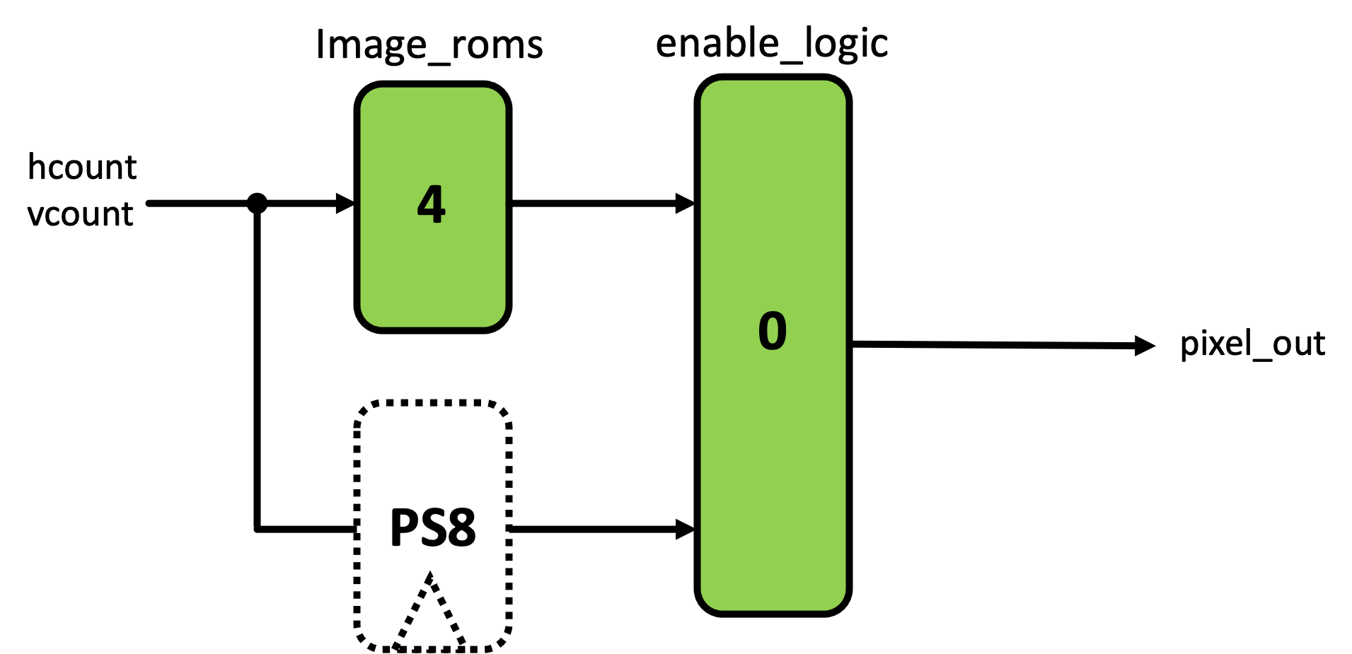
Your center of mass should be working and you should be tracking things, but the system is also horribly pipelined at this point. The propagation of information via various routes through the system get delayed differing amounts resulting in data from one point in time getting used with data from another point in time. It is awful. A very obvious way in which this should manifest is that you'll see a large bar of pixels on the left side of your screen that are actually from the right side of the screen. This is because we haven't balanced the hsync and vsync signals with the pixel data. Another, less obvious issue is that as we've discussed in lecture 7, accessing information from a image on our FPGA takes four clock cycles. Consequentily when rendering your Image Sprite, you're going to see an artifact of that in the top left (of the sprite) consisting of several white pixels; depending on your implementation, your edges may also have problem. You should make sure that you properly pipeline your entire system to account for these delays. What signals will this require you to pipeline? The crosshair and the RGB to YCrCb conversion also have their own problems.
The input to hsync and vsync signals aren't the only path that has problems. The input signals to the center of mass are also poorly pipelined at this point meaning you'll be counting the wrong pixel locations. This also needs to be fixed.
The entire state of our pipelining is shown in the schematic below (this does not contain all signals...only ones relevant to the pipelining problem). The modules marked in green already exist and the number inside them indicates their latency in clock cycles on 65 MHz. As just stated, there are two pipelines we currently have to worry about balancing: (start-to-endpoint1 and start-to-endpoint2). These both bust be made into well-balanced, k- pipelines. While they are separate, they are not independent, based on how the signals are used in both.
What we would like to do is balance both pipelines so each Start-to-Endpoint is well-balanced in terms of latency. This can be accomplished by placing the correct amount of registers into the seven locations shown below. Study the figure, and determine the seven numbers. (Note while there are infinite solutions that will result in a well balanced
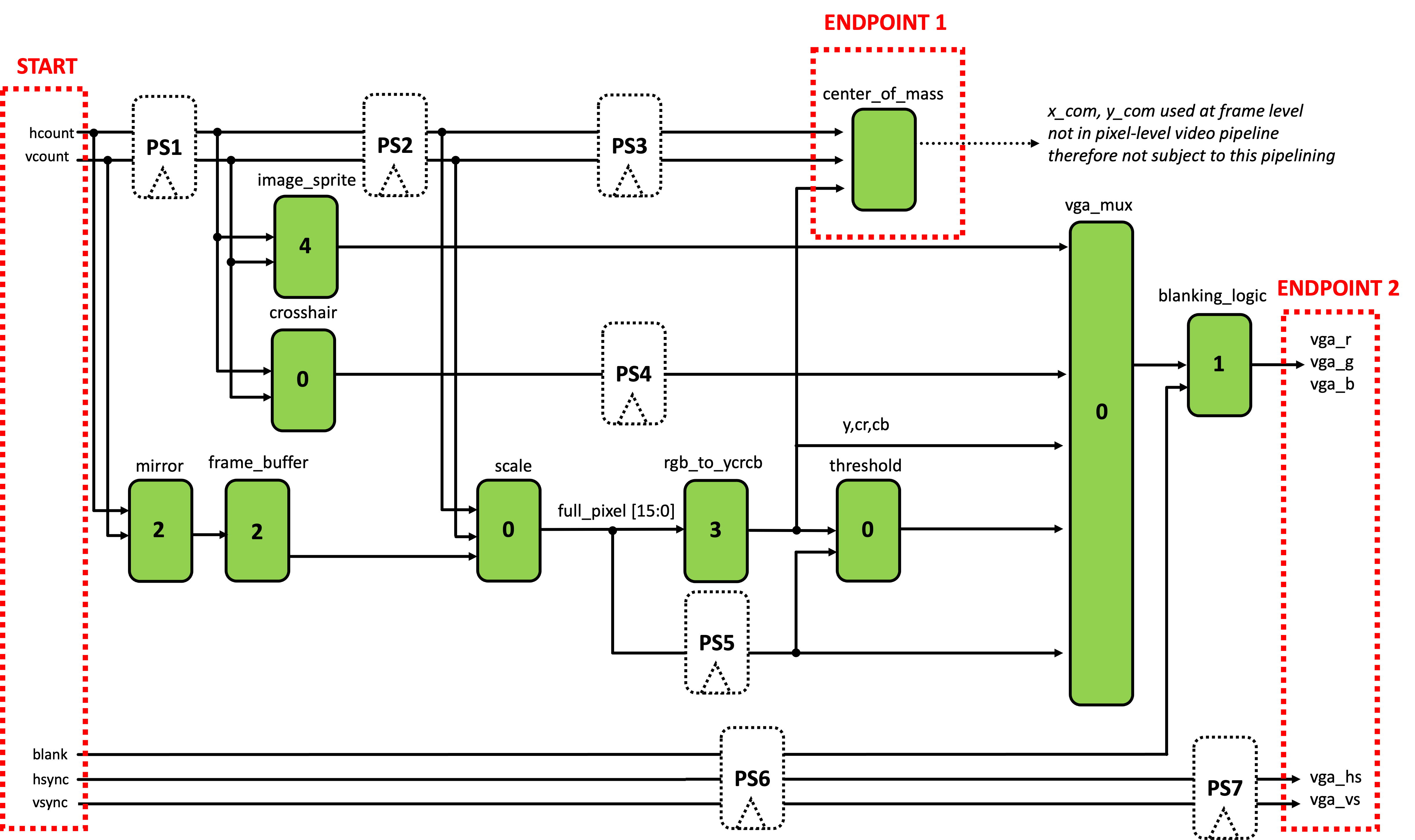
In the seven boxes below, enter the correct number of registers needed to balance both pipelines.
Now that we know where and how to pipeline our system, we need to implement it in Verilog. The easiest way to do this will be to create a series of appropriately-sized unpacked array for the signals that need to be pipelined. For example, hcount definitely needs pipelining. We could accomplish creating of a pipeline with the following (which could be implemented in top_level:
//vary the packed width based on signal
//vary the unpacked width based on pipeling depth needed
logic [10:0] hcount_pipe [STAGES_NEEDED-1:0];

always_ff @(posedge clk_65mhz)begin
  hcount_pipe[0] <= hcount;
  for (int i=1; i<STAGES_NEEDED; i = i+1)begin
    hcount_pipe[i] <= hcount_pipe[i-1];
  end
end
Then replace the appropriate instances of hcount in your code. For your aid/convenience they have been marked with a //TODO... line with some notes, but make sure you are double-checking everything5. For example in the image_sprite, you'll see this line:
.hcount_in(hcount), //TODO: needs to use pipelined signal (PS1)
You'd want to replace this with something like:
.hcount_in(hcount_pipe[BLAH]), //BLAH corresponds to your pipelined value for PS1!
Another location where a pipelining mismatch will occur is likely inside your image_sprite module. The logic that "releases" the image data is not synced in time with the data coming from the BRAM. So fix it!
When you've completed this pipelining, your system should still work as before, but slightly better! You should see significantly less "wrong" stuff on the left side of the screen, for example. There should also NOT be an artifact where your image sprite is being drawn (upper left corner white pixels).
Show staff how you pipelined and what signals you pipelined.
If you want some sweet sweet extra credit, integrate your pong game from lab03 such that your object tracking moves the paddle up and down. We won't require you to worry about alpha blending, paddle speed limits, variable puck speed, or the random initial starting conditions. Just having a puck that bounces off a controllable paddle and the edges of the screen is enough. Or if you wanna implement the fancy stuff, go for it. Flex on us.
Feel free to swap out the pink screen that's displayed when sw[9:8]==2'b11 is selected with your pong game.