Microphone UART Upload
testing, testing, 1,2,1,2
Please Log In for full access to the web site.
Note that this link will take you to an external site (https://shimmer.mit.edu) to authenticate, and then you will be redirected back to this page.
Overview
In this checkoff, you'll begin using UART to communicate between your FPGA board and your computer. You've already built a UART transmitter; now you'll put it to use by transmitting real data from the FPGA to a Python script running on your computer. But what data should we send?
We'll use the MAX9814 microphone to capture audio. The microphone produces an analog voltage signal, which we'll sample using the MCP3008 analog-to-digital converter (ADC) from last week. The FPGA will collect these audio samples and do two things with them:
- Play them back through the board's audio output.
- Send them over UART to your computer, where a Python script will save them as a
.wavfile.
By the end of the checkoff, you'll have built the following system:
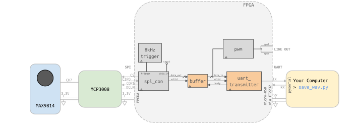
There are two main data paths operating at the same time:
- Audio capture: The FPGA periodically communicates with the MCP3008 over SPI to sample the microphone signal. Each new audio sample is stored in a small buffer.
- Audio output and transfer: Samples are read from the buffer and sent both to the board's audio output and to the UART transmitter, which sends them to your computer.
This means that while one part of your design is continuously producing samples, another part is continuously consuming them.
Files and Setup
Create a new lab directory with the directory structure you're familiar with from the previous labs: hdl, xdc, sim, and obj. Collect the following files to get started:
-
hdl/top_level.sv: Basetop_levelfile for this lab.pwm.svfrom Week 01: We'll repurpose this to reconstruct an audio signal. Make sure you're using the version discussed in lecture with no division or modulo. Otherwise, this lab will not work well.spi_con.svfrom Week 02: We'll continue using this to communicate with the MCP3008 over SPI.uart_transmit.sv: Use the UART transmitter from the exercise you just completed.
-
xdc/top_level.xdc: Start with the version from the end of Week 02, including the changes used to label the SPI wires.- Uncomment the lines for
spkl,spkr,uart_rxd, anduart_txd. - Rename
pmodb[5:0]to the corresponding debug signal names listed intop_level.sv. We'll use these later to inspect both the SPI and UART waveforms with the logic analyzer.
-
ctrl/- This is a new directory for the computer-side Python scripts we'll use to communicate with the FPGA.
- Keep
ctrl/one level above your lab directory so it doesn't get mixed in with your FPGA build files. test_ports.py: Finds the serial port connected to your FPGA board. See the Finding Your Serial Port section below.save_wav.py: Receives audio samples from the FPGA over UART and saves them to a.wavfile.
I. Capturing Audio Samples at 8 ksps over SPI
Let's start at the beginning of our data path: capturing audio from the microphone.
Last week, we used the MCP3008 analog-to-digital converter (ADC) to measure the analog voltage from potentiometer knobs. But there's a whole world of analog phenomena we can capture with an ADC! One thing that immediately comes to mind is audio.
Sound is made up of pressure waves traveling through the air. We can use a microphone to convert these pressure waves into an analog voltage signal with a corresponding frequency and relative amplitude. The microphone board we'll use for this lab is the MAX9814:
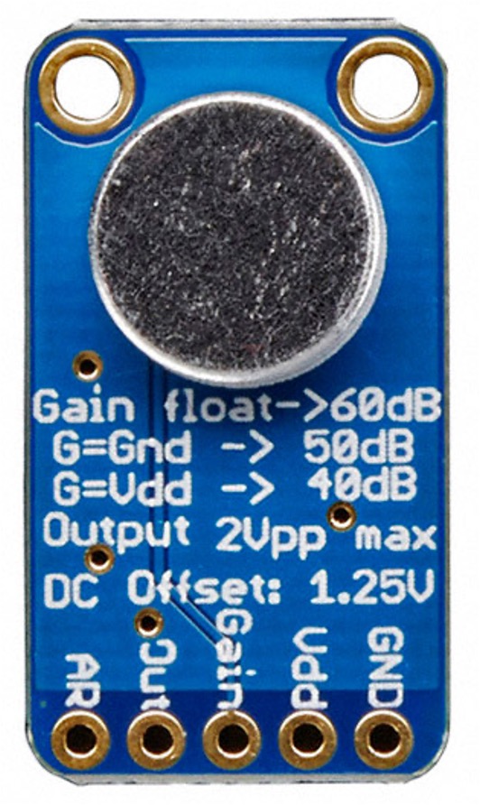
The MAX9814 board is a pretty nice little setup. The microphone itself handles the pressure-to-voltage conversion, turning sound waves into an electrical signal. The board also includes an on-board amplifier with Automatic Gain Control (AGC). The AGC automatically adjusts the amplifier's gain to keep the output signal at a relatively consistent amplitude. This is especially useful for human speech, since the volume of our voices can change quickly. Without AGC, quiet sounds might produce signals that are too small, while loud sounds could cause clipping. Using feedback, the AGC continuously adjusts the gain to keep the audio signal within a useful range.
Human ears can hear frequencies up to about 20 kHz. In practice, unless you're listening to Mariah Carey in her prime or some other unusually high-frequency sounds, much of the information needed to understand human speech lies below about 3 kHz.1
According to the Nyquist-Shannon Sampling Theorem, to capture a signal containing frequencies up to f_{\text{max}}, we need to sample at a rate greater than 2f_{\text{max}}. We'll get into the details (and some important caveats!) later in the semester.
For speech content up to about 3 kHz, this means we need to sample at more than 6,000 samples per second (6 ksps). For this lab, we'll use a sampling rate of 8 ksps.
Setting Up the SPI Controller for Audio
To sample our microphone at 8 ksps, we need to request a new sample from the MCP3008 ADC once every 1/8000 of a second. Since our SPI controller begins a transaction when it receives a trigger, we'll need to generate a single-cycle trigger at 8 kHz.

Now, let's configure the SPI side of the design:
-
Generate the periodic sampling trigger. Use the
countermodule from Week 01 to count the clock cycles between samples. Configure it in yourtop_levelmodule and use it to generate the periodic single-cycle, 8 kHz trigger. -
Request samples from
CH7. The microphone output is connected toCH7of the MCP3008, and we won't need to read from any of the other ADC channels. This means the message we send to the MCP3008 over SPI will always be the same. Based on how you selected ADC channels last week, assignspi_write_datato a constant value that requests a sample fromCH7. -
Capture the audio sample. Create an 8-bit register called
audio_sampleand use it to store the appropriate bits returned by the MCP3008.2 Only updateaudio_samplewhen the SPI controller indicates that the returned data is valid.
II. Audio Out with PWM
Now that we're capturing a new audio sample at 8 ksps, let's listen to what we're recording!
We'll use the 3.5 mm line-out audio port on the top-left of the board. Our microphone samples are digital values, but our headphones ultimately need an analog signal. This is similar to what we did with the LEDs in Week 01: we used a digital output to control an analog quantity. For the LEDs, that analog quantity was brightness. Here, it's the amplitude of our audio signal.
Once again, we'll use Pulse-Width Modulation (PWM).
From LED Brightness to Audio
When we used PWM to control an LED, we rapidly switched the LED on and off according to some duty cycle. When this switching happens fast enough, our eyes don't perceive each individual pulse. Instead, we perceive their average effect as a particular brightness level controlled by the duty cycle. See the diagram below:
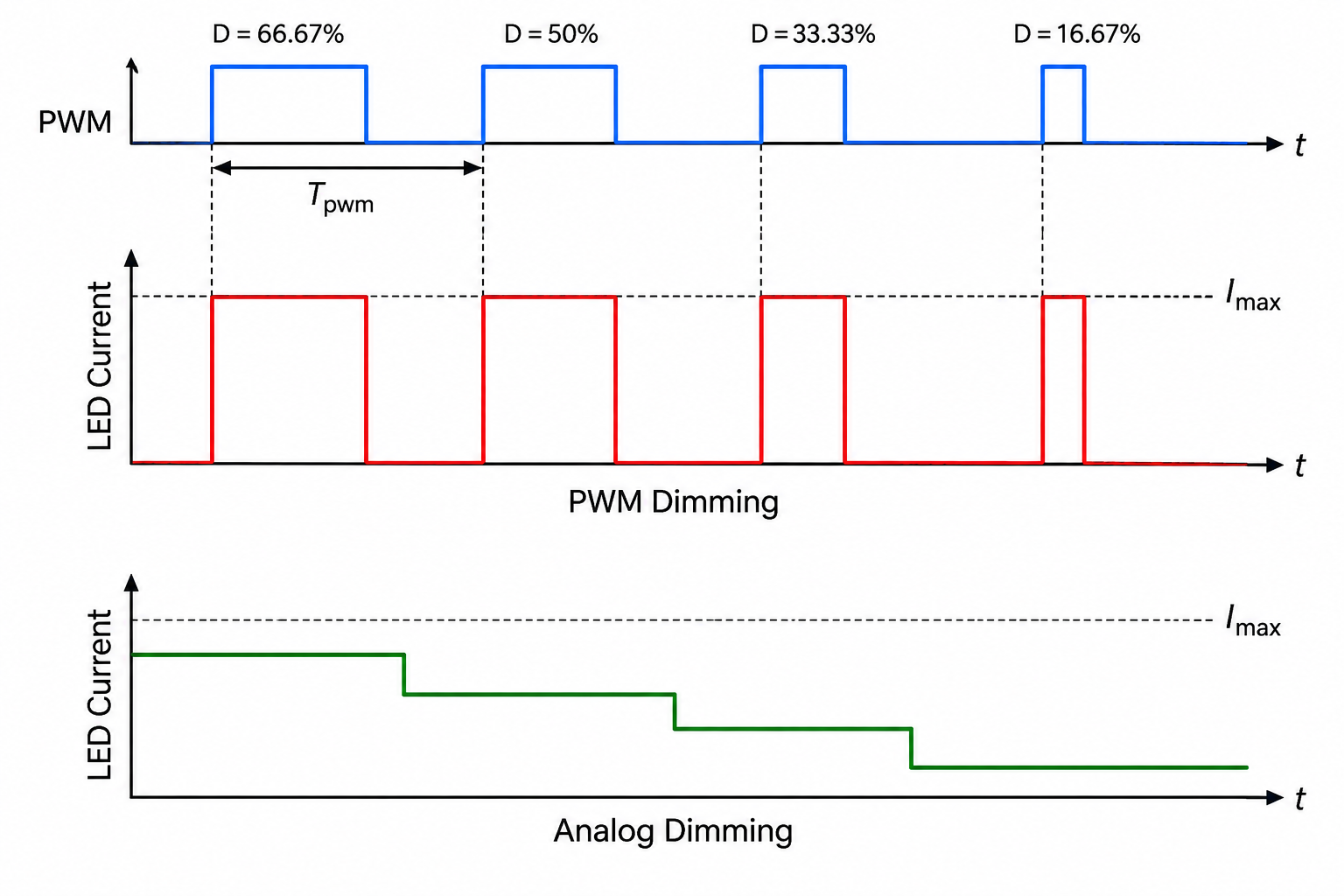
The same basic idea can be used for audio. Instead of using the PWM duty cycle to represent LED brightness, we'll use it to represent the amplitude of each audio sample.
There's one important difference: the LED brightness we wanted was steady, while audio is a waveform whose amplitude changes over time. As our audio samples change, the PWM duty cycle must change with them.
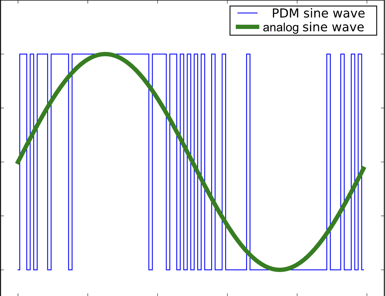
Before we implement that, let's make sure the math works. There's an important difference between the two cases above: our ears are much more sensitive to fast changes than our eyes!
When controlling an LED, we only needed the PWM switching to be fast enough that we no longer perceived the individual on/off pulses. Our PWM frequency was already much faster than what we needed for that.
Let's check the PWM module you built earlier:
That's plenty fast for controlling LED brightness. But can we use the same PWM module for audio?
Human hearing extends to roughly 20 kHz. If we want the PWM switching itself to lie above the frequencies we're trying to reproduce, our PWM frequency needs to be significantly higher than our audio frequencies.
Again, our PWM carrier is much faster than both our 8 kHz sample rate and the frequencies we're trying to reproduce. That's good enough for our purposes in this lab.3
Driving the Audio Output
Let's instantiate the pwm module in top_level and use it to drive the board's audio output.
The audio samples coming from the ADC will determine the PWM duty cycle, and the resulting PWM signal will be connected to the board's audio output.
Do not send the full-scale ADC samples directly to your headphones.
The resulting audio can be very loud. Before passing audio_sample into the PWM module, the provided design scales the signal down by approximately a factor of 8. In hardware, this can be done very cheaply by shifting the value right by 3 bits.
This reduces the available audio resolution, but that's okay for this lab.4
Also be careful about placing the microphone near your headphones while audio is playing. The microphone can pick up the audio output, amplify it again, and create some terrible feedback.
When testing for the first time, don't put the headphones all the way into your ears.
top_level.sv file.
Give It a Listen!
At this point, you should have the complete audio path:
Microphone → ADC → SPI → audio_sample → PWM → Audio Out
Build your design in Vivado and program your FPGA. Plug a pair of wired headphones into the board's audio jack and try speaking into the microphone. You should hear the captured audio played back through your headphones!
If you need wired headphones, grab a pair from the front of the lab. If you grab a pair of in-ear headphones, please keep them when you're done—don't put them back, because that's gross. Consider them a present from us.5
III. UART Transmitter
Now that we know we're successfully capturing audio samples, it's time to make that data escape FPGA-land and end up in a file on our computer!
We'll use the UART transmitter you just built to send each 8-bit audio sample from the FPGA to a Python script running on your computer.
As we learned when implementing UART, the protocol itself only needs two wires: one for transmit and one for receive. But we can't exactly run two wires from FPGA pins directly into our laptops. The connection available to us is the micro-USB cable you've already been using to program your board.
That's where the FTDI2232 chip comes in.
The FTDI2232 is part of the Urbana development board and acts as a bridge between the FPGA and USB. USB is a much more complicated protocol that we couldn't reasonably ask you to implement in this lab.6
The FTDI chip has already been helping us communicate with the board when programming the FPGA. Now we'll use its UART interface: our FPGA sends ordinary UART data to the FTDI chip, and the FTDI handles the USB side so that those bytes eventually show up in a Python script on our computer.
Hold That Thought: Keeping Samples While UART Is Busy
Before we start sending samples over UART, there's one problem we need to deal with.
Our SPI controller and UART transmitter operate independently. The SPI controller produces a new audio sample every 1/8000th of a second, while the UART transmitter takes some amount of time to send each byte.
We need to make sure of two things:
-
UART must be fast enough to keep up with our audio samples. If a new audio sample arrives while UART is still transmitting the previous sample, we need somewhere to hold it. If another sample arrives before we've handled the first one, we'll start dropping samples.
-
Each sample should be transmitted exactly once. If UART finishes transmitting before the next audio sample arrives, we don't want to accidentally transmit the same sample again.
To handle this, we'll add a small amount of control logic between our SPI controller and UART transmitter.
Create a signal called audio_sample_waiting:
- Set
audio_sample_waitinghigh whenever the SPI controller produces a new valid audio sample. - Keep it high while the UART transmitter is busy.
- Once UART is available and the sample is handed to the UART transmitter, set
audio_sample_waitingback low.
In other words, audio_sample_waiting tells us:
"I have a new audio sample that has not been transmitted yet."
You should also combinationally control the valid input to uart_transmit so that data is only sent when sw[0] is turned on. This gives us a simple way to start transmitting only once the computer is ready to receive data.
Choosing the UART Baud Rate
Now we need to make sure UART can actually keep up with our 8 ksps audio stream.
We're sending one byte for every audio sample. Remember, though, that sending one byte over UART requires more than 8 transmitted bits because each UART frame also contains a start bit and a stop bit.
Choose a baud rate higher than the minimum you just calculated. Baud rates can theoretically take many values, but it's convenient to choose from commonly used standard rates:
4800, 9600, 19200, 38400, 57600, 115200, 230400, 460800, 921600
Don't choose an unnecessarily high baud rate: as the baud rate increases, the timing requirements become tighter and communication becomes less tolerant of clock mismatch and other imperfections.
Instantiate your uart_transmit module using your chosen baud rate. Connect the audio data and control signals you configured above, and connect the transmitter output to the uart_txd top-level port.
The signal path now looks like:
audio_sample → waiting logic → uart_transmit → uart_txd → FTDI2232 → USB → Computer
Listening on the Computer's Side
Since we're aiming to talk to our computers from the FPGA board, we need to talk about how we'll actually make our computers listen! What we want is a Python script that can listen to the UART_TX wire output and interpret those bytes as numbers. Python has a library called pyserial that provides the functionality to talk or listen on a UART port, and that's what we'll use here.
For this lab, we've written the Python script for you, but take a look at the script! It's not too complicated, and following the pattern of the provided script will let you work in Python with any data you send up from your FPGA.
In order to use pyserial, you'll need to install it. You already have a Python environment running from setting up cocotb, so with that environment activated, run pip install pyserial (or a similar command) to install it!
In the Python script we've provided for you, you need to specify the SERIAL_PORT_NAME for pyserial to use when looking for UART data. Depending on your operating system, the string needed to select the proper serial port for your board will look different. Luckily, pyserial has a tool built into it to see your available ports. This test script will find all the available ports and test sending data over each one to find the correct port to use.
With your board plugged in and turned on, run the above script to see all the serial ports available to you. There may be a handful of different serial ports that appear, but the ones we're interested in are manufactured by Xilinx and are described as JTAG+Serial.
On Ubuntu (or Ubuntu in WSL with the board attached the same way as for flashing), the results we're looking for will look something like:
Ports found:
/dev/ttyUSB1: JTAG+Serial - JTAG+Serial [manufacturer: Xilinx]
/dev/ttyUSB0: JTAG+Serial - JTAG+Serial [manufacturer: Xilinx]
The serial port names in this case are the names on the left: /dev/ttyUSB1 and /dev/ttyUSB0. On Windows, the port names will instead look something like COM7 (or some other number).
Note for the Windows folks: WSL will probably make your (and our) life easier in this case. It is possible to get the script to work with Windows Python, but you must have the WinUSB driver (from Zadig) installed for the flashing interface and the original FTDIBUS driver (replaced with Zadig) installed for the serial interface. This process can be a pain...
Following the prompts, test sending data over UART to the Xilinx ports. The test will send some messages over UART, and you can tell the board is actually receiving them if the TX LED (near the USB port) starts flashing green. Typically, two ports will be labeled as Xilinx, and only one of them is good for UART communication!
Once you find the port that successfully sends data to the board, replace <YOUR SERIAL PORT HERE> in this checkoff's Python script with the port name you found. Keep a note of it for any future use of UART!
Now that you know the name of your serial port, set the variable in save_wav.py appropriately and set the BAUD rate appropriately. Build your design and flash it to the board!
Once it's running, start up your listener script with python3 save_wav.py, and then switch sw[0] on to allow your UART module to start running. Leave sw[0] on for a few seconds and say something into the microphone, then turn sw[0] off again.
After your computer sees silence for a couple of seconds, it'll save the audio samples you sent to a .wav file, which you can play with any audio file player on your computer.
Viewing Waves With the Logic Analyzer
At the end of top_level's port declarations we've added the following debug ports:
    //debug ports:
    output logic debug_copi,        //change name of pmodb[0] in default xdc
    output logic debug_cipo,        //change name of pmodb[1] in default xdc
    output logic debug_dclk,        //change name of pmodb[2] in default xdc
    output logic debug_cs,          //change name of pmodb[3] in default xdc
    output logic debug_uart_rxd,    //change name of pmodb[4] in default xdc
    output logic debug_uart_txd     //change name of pmodb[5] in default xdc
    );
which are connected to relevant bus signals a few lines below that point:
    //debug connections:
    assign debug_copi       = copi;
    assign debug_cipo       = cipo;
    assign debug_dclk       = dclk;
    assign debug_cs         = cs;
    assign debug_uart_rxd   = uart_rxd;
    assign debug_uart_txd   = uart_txd;
Breaking these signals out allows a convenient means of viewing them in real life with the logic analyzer and, if needed, debugging. Connect six channels of your logic analyzer (and ground) up to the appropriate pins on the FPGA and run a couple waveform captures using either cs as the trigger or uart_txd as the trigger so you can see what waveforms are showing up where. You will need to show and discuss this for your checkoff below. A reminder of the pinout is shown below for convenience (taken from Week 1).
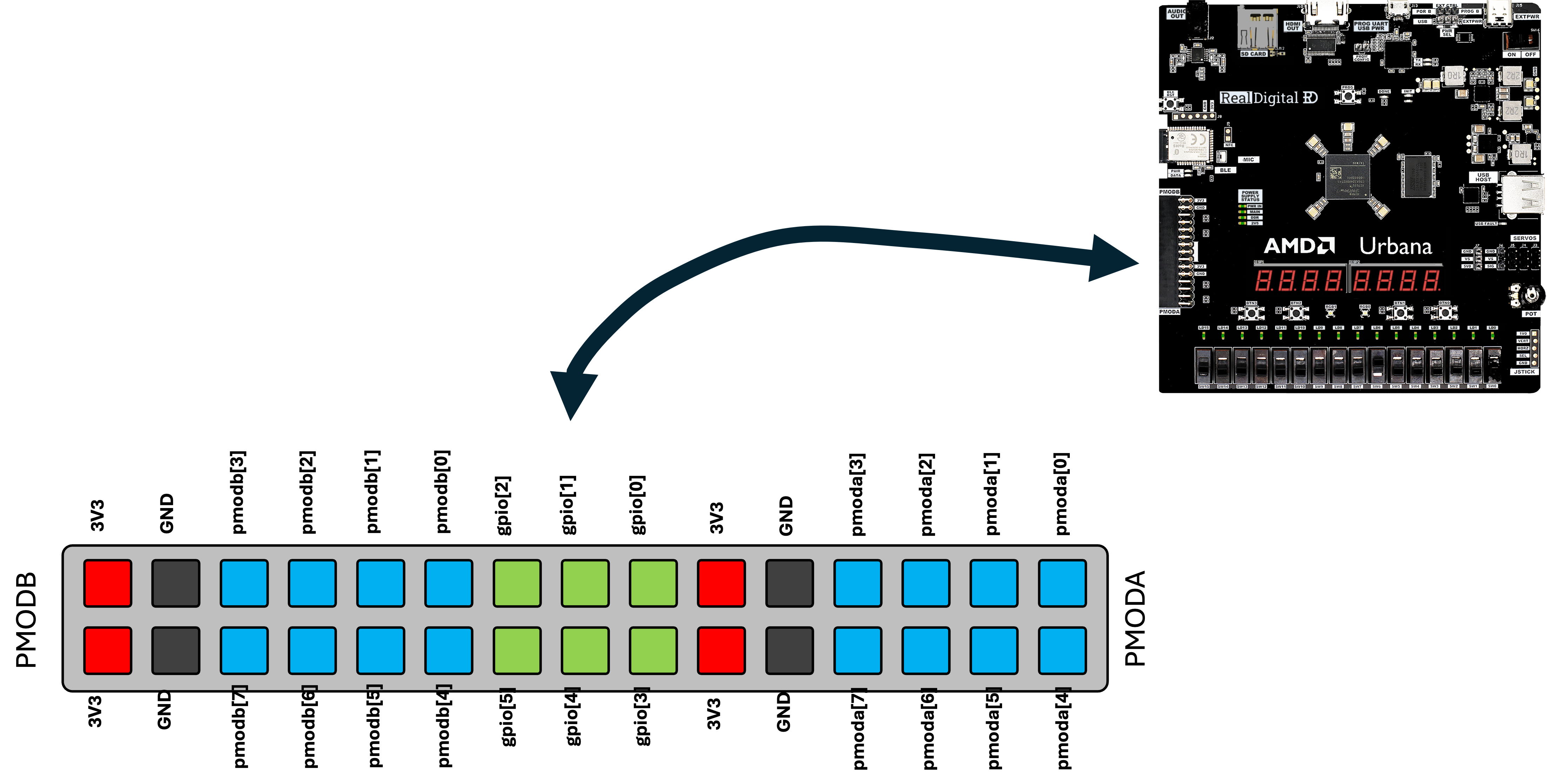
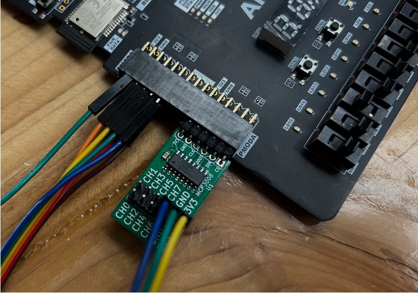
For this testing, instead of using the grabby-wires, just use seven pin/socket wires from the front of the room since they'll fit better into the connector.
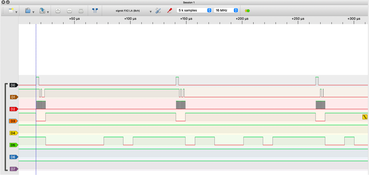
An example of what should be seen on the six debug channels is shown below. A trigger is set on the falling edge of CS and the SPI signals from last week should be visible as well as the appropriate signal being sent up over UART following shortly thereafter. Note the different in bit rate.
Show a staff member your system capturing an audio recording from the MAX microphone, and the audio playing out of your line out port. Have a logic analyzer waveform up showing the appropriate signals on both the SPI bus and the UART Bus. Be prepared to explain the bits on all the channels and to explain what they are. Inability to do so, will result in you not getting the checkoff. No Checkoff without a real-time signal trace. Be ready to talk about the BAUD rate you chose, how you set up your trigger, and the buffer logic you wrote to preserve your audio samples.
Footnotes
1There is definitely useful information at higher frequencies, but much of what is needed for speech intelligibility is concentrated at lower frequencies.
2Why store 8 bits instead of all 10 bits from the ADC? We'll eventually write these samples to a .wav file on the computer, so using 8-bit samples makes our data line up nicely with byte-oriented storage.
3This is still a very simple way to generate audio, and some PWM artifacts may make it through. If you work with audio in your final project, you may want to investigate techniques such as filtering or Pulse-Density Modulation (PDM) for higher-quality output.
4Pretty much everything we're doing in this lab sacrifices some audio quality for simplicity :) If you use audio in your final project, think about how you could preserve more of the original signal resolution.
5If you don't trust your design yet, this might not be the time to test it with your fanciest, most expensive headphones...
6Lest this class end up with an hour rating like power electronics... I hope our friends making audio square waves on the other side of the lab get some sleep :)