Please Log In for full access to the web site.
Note that this link will take you to an external site (https://shimmer.mit.edu) to authenticate, and then you will be redirected back to this page.
IcarusVerilog (or iVerilog for short) is a open-source Verilog simulation and synthesis tool we use for making fast simulations of Verilog projects. iVerilog works on all three families of operating systems. Details for different operating systems are provided on this site. A few notes from our experience:
- If you're on Mac, just install it using homebrew. That seems to be the least painful.
- If you're using Linux, just use whatever instructions you like. I've had no problem with both Debian and Ubuntu for what it is worth.
- If you're on Windows, it's best to just use the installer. There's a link to the installer page at the bottom of the official docs, or you can grab it here. Make sure to check the box to add the executable folders to the path when you install. There's also an option in the installer to also install GTKWave, feel free to check that too.
We'll also need to install GTKWave as well. This is a good lightweight waveform viewer, used for displaying simulation output. Detailed install instructions can be found here, and shouldn't need any significant changes, but we've found:
- If you're on Windows and you already installed GTKWave at the same time you installed iVerilog, there's no need to install it again.
- macOS people will probably have the easiest time installing from homebrew with
brew install --cask gtkwave. You might need to go theGeneraltab under yourSecurity and Privacysettings and manually allow GTKWave to run. - Debian/Ubuntu folks, if you did everything for iVerilog already, you likely can just
apt installgtkwave.
Make a folder, and create the the following files inside it:
example.sv: A file that will contain a very simple module for us to testexample_tb.sv: A testbench for example.sv, where we'll have some code to test the module inexample.sv
Copy the following code into example.sv:
`timescale 1ns / 1ps
`default_nettype none

// a simple module that will increment c_out on the clock edge if a_in > b_in
// otherwise, c_out doesn't change.
module example (
        input wire          clk_in,
        input wire          rst_in,
        input wire [5:0]    a_in,
        input wire [5:0]    b_in,
        output logic [4:0]  c_out);

  always_ff @(posedge clk_in) begin
    if (rst_in) begin
      // reset to 0
      c_out <= 0;
    end else begin
      c_out <= (a_in > b_in) ? c_out : c_out + 1;
    end
  end
endmodule

`default_nettype wire
Copy the following code into example_tb.sv:
`timescale 1ns / 1ps
`default_nettype none
module example_tb();

    logic clk_in;
    logic rst_in;
    logic [5:0] a_in, b_in;
    logic [4:0] c_out;

    example uut(  .clk_in(clk_in),
                  .rst_in(rst_in),
                  .a_in(a_in),
                  .b_in(b_in),
                  .c_out(c_out));

    always begin
        #5;  //every 5 ns switch...so period of clock is 10 ns...100 MHz clock
        clk_in = !clk_in;
    end

    //initial block...this is our test simulation
    initial begin
        $dumpfile("example.vcd"); //file to store value change dump (vcd)
        $dumpvars(0,example_tb); //store everything at the current level and below
        $display("Starting Sim"); //print nice message at start
        clk_in = 0; //0 is generally a safe value to initialize with and not specify size
        rst_in = 0;
        a_in = 0;
        b_in = 0;
        #10
        rst_in = 1; //always good to reset
        #10
        rst_in = 0;
        $display("a_in    b_in    c_out");
        for (integer i=0; i<256; i = i+1)begin
          for (integer j=0; j<256; j= j+1)begin
            a_in = i;
            b_in = j;
            #10; //wait
            $display("%8b %8b %5c",a_in, b_in, c_out); //print values C-style formatting
          end
        end
        $display("Finishing Sim"); //print nice message at end
        $finish;
    end
endmodule
`default_nettype wire
Once your source files are ready, we'll use this command to run the simulation:
iverilog -g2012 -o example.out example_tb.sv example.sv
Let's break down what each component means:
iverilogcalls the program-g2012tells iVerilog to read the source files as SystemVerilog (specifically the SystemVerilog defined in IEEE 1800-2012)-o example.outplaces the simulation output in the fileexample.outexample_tb.svandexample.sv, are the source files that contain what we want to simulate. If you had other source files, they'd go here too.
When you run this command, you should get an error message like this:
example_tb.sv:10: syntax error
example_tb.sv:15: error: invalid module item.
This is an example of how/when/where a compile-time-error in your Verilog would show up. In this case, line 8 in example_tb.sv is missing a semicolon at the end:
logic [4:0] c_out
Fix that, then rerun the simulation with the same command. If nothing shows up, good! This means the compiler ran with no errors. Inside your folder there should now a file called example.out, which is a compiled version of your testbench.
When we run the iverilog command, we used iVerilog to compile your Verilog testbench to an executable file. Now, We'll now want to run that executable file inside vvp, which is the Verilog runtime that comes bundled with iVerilog. When we do this, we simulate the module, logging the values of the internal signals along the way. Go ahead and try this with:
vvp example.out
You should see tons of values fly by - these are the output of the $display statements we made in the testbench. These statements are super useful for debugging, and we can view our results as waveforms too.
In addition to the text output from our simulation, we can also view the signals in the design as waveforms. Our simulation actually already generated the Value Change Dump (VCD) file needed for this, as you can see from the following lines in the testbench:
    // store the simulation output as a Value Change Dump (VCD) file
    $dumpfile("example.vcd");

    // store everything at the current level and below
    $dumpvars(0, example_tb);
This tells the simulator to store the value of every signal in the simulation at every time step. This goes into a .vcd file, which is a standard digital signal file format that's viewable with a waveform viewer. There's multiple ones out there, but we recommend GTKWave since it is cross-platform and is relatively suck-free. 1 If you're on Windows or Linux, from a terminal you can just run:
gtkwave example.vcd
This will likely not work for people on MacOS - for some reason GTKWave doesn't like being called from the command line. Assuming it actually installed, you can probably get away with launching it from your Launchpad, and then opening .vcd file from there.
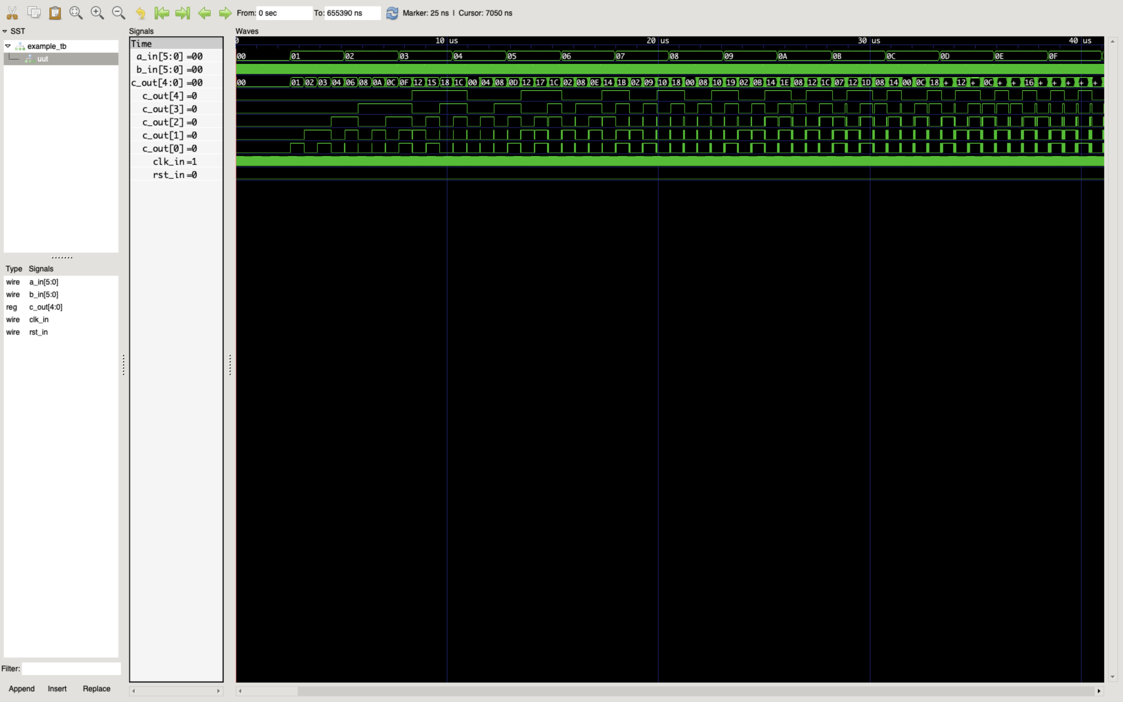
Regardless, once you've loaded this vcd file, you can add your signals to the waveform viewer by highlighting which modules and signals you care about, clicking "Insert" and then, moving around/zooming, etc. If you later make a change to your code, you can then just simply:
- Recompile with
iverilog -g2012 -o example.out example_tb.sv example.sv - Run simulation with
vvp example.out - Reload the waveform from the file menu in GTKWave. Easy peasy.