Oscilloscope Guide
How to Measure and Trigger Signals on the Scope
Please Log In for full access to the web site.
Note that this link will take you to an external site (https://shimmer.mit.edu) to authenticate, and then you will be redirected back to this page.
Channels and Ground
An oscilloscope measures voltage, and voltage is always measured relative to something. That something is ground. Every probe has two connections the tip (signal you wanna measure) and the ground clip (reference/GND). If you don't connect the ground clip, the scope has no reference to compare against and you'll get garbage,nonsense, or potentially signals from distant galaxies.
So please hook your probe's ground to GROUND, since we'll mainly be probing signals on our FPGA this typically means you connect one end of a wire to the GND PMOD, and the other end to the gnd clip.
You might also notice your scope has multiple channels, this whole example I'm working with channel 1, but with the bright coloring and labeling on the scope I'll believe once you understand channel 1 you'll understand the rest.
Horizontal Scale (Time)
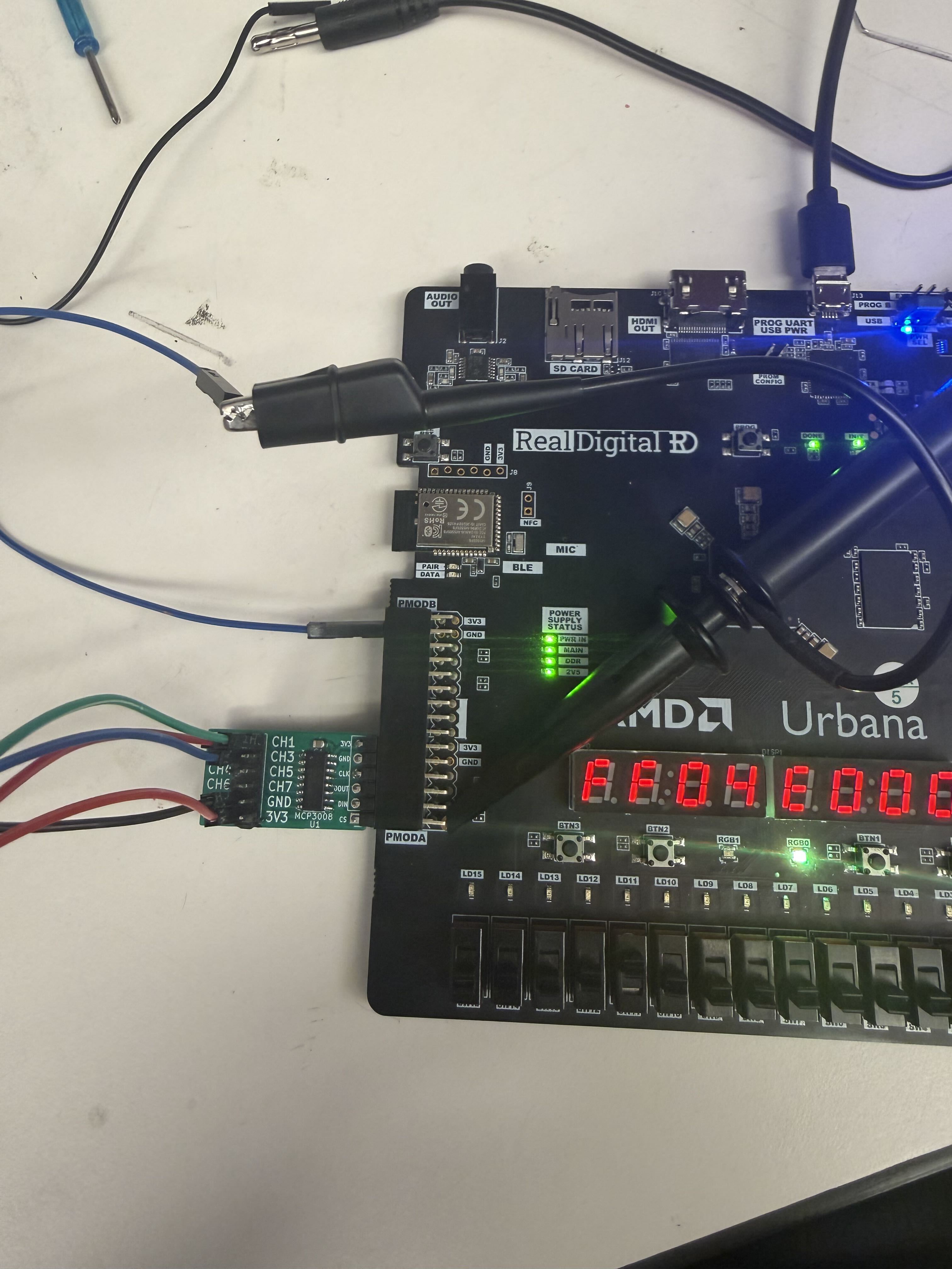
The horizontal knob controls your time base: how many seconds (or micro/nanoseconds) each division across the screen represents. Zooming out, zooms out in time fitting more of your signal on screen. Zooming in, zooms in in time, stretching a tiny part of time across the whole screen so you can see cool details(like rise time, or the exact edge of the clock)
Vertical Scale (Voltage)
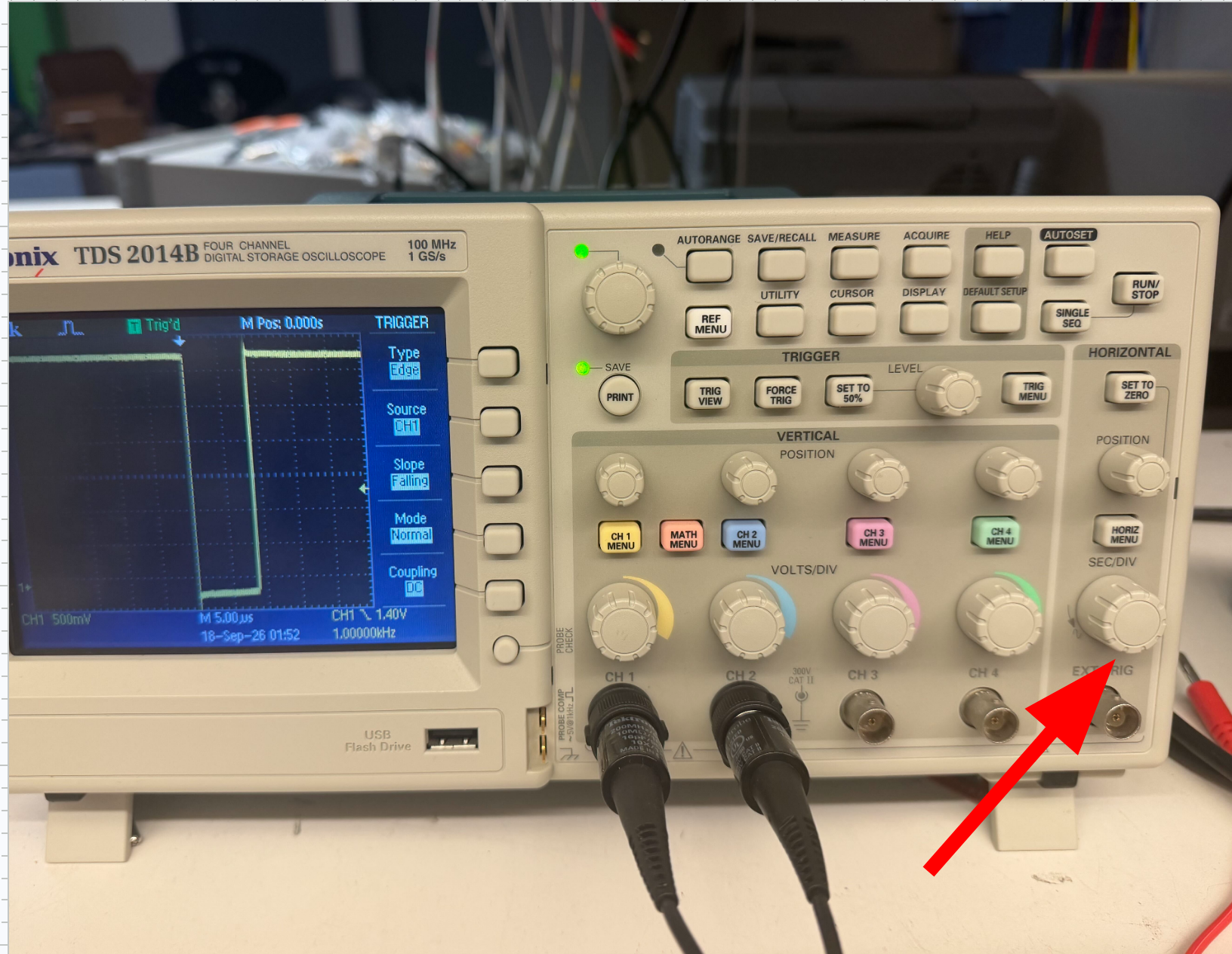
The vertical knob sets the volts-per-division on screen. Zoom out to fit a big signal on the screen. Zoom in to see small stuff or tiny signals, or cause you zoomed too far out and need to fix it.
Triggering
Instead of relying on luck to catch a specific event(like our CS dropping low in lab 2), we can tell our scope to only update when it detects that event. These events are usually called triggers.
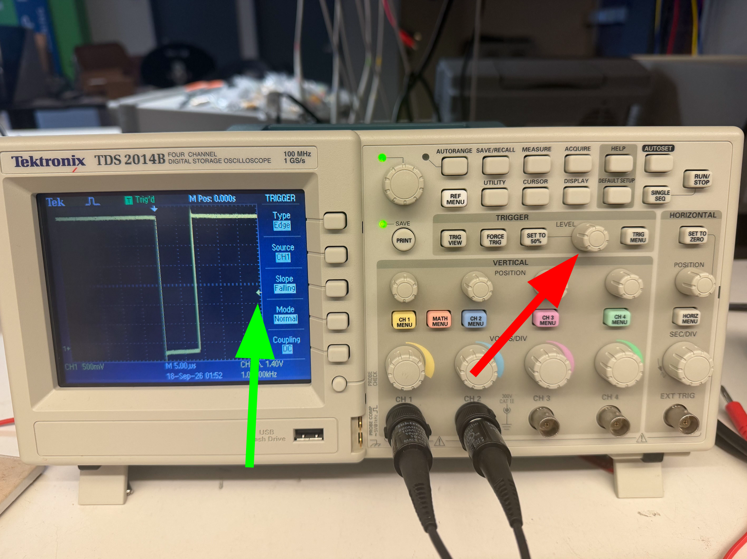
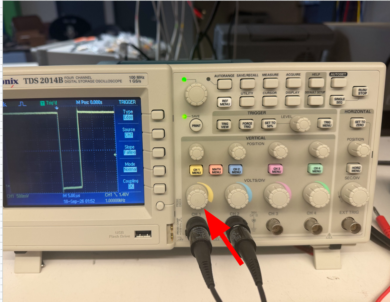
Firstly if you wanna mess with triggers you should probably change the menu to the trigger menu so you can change the trigger related values.
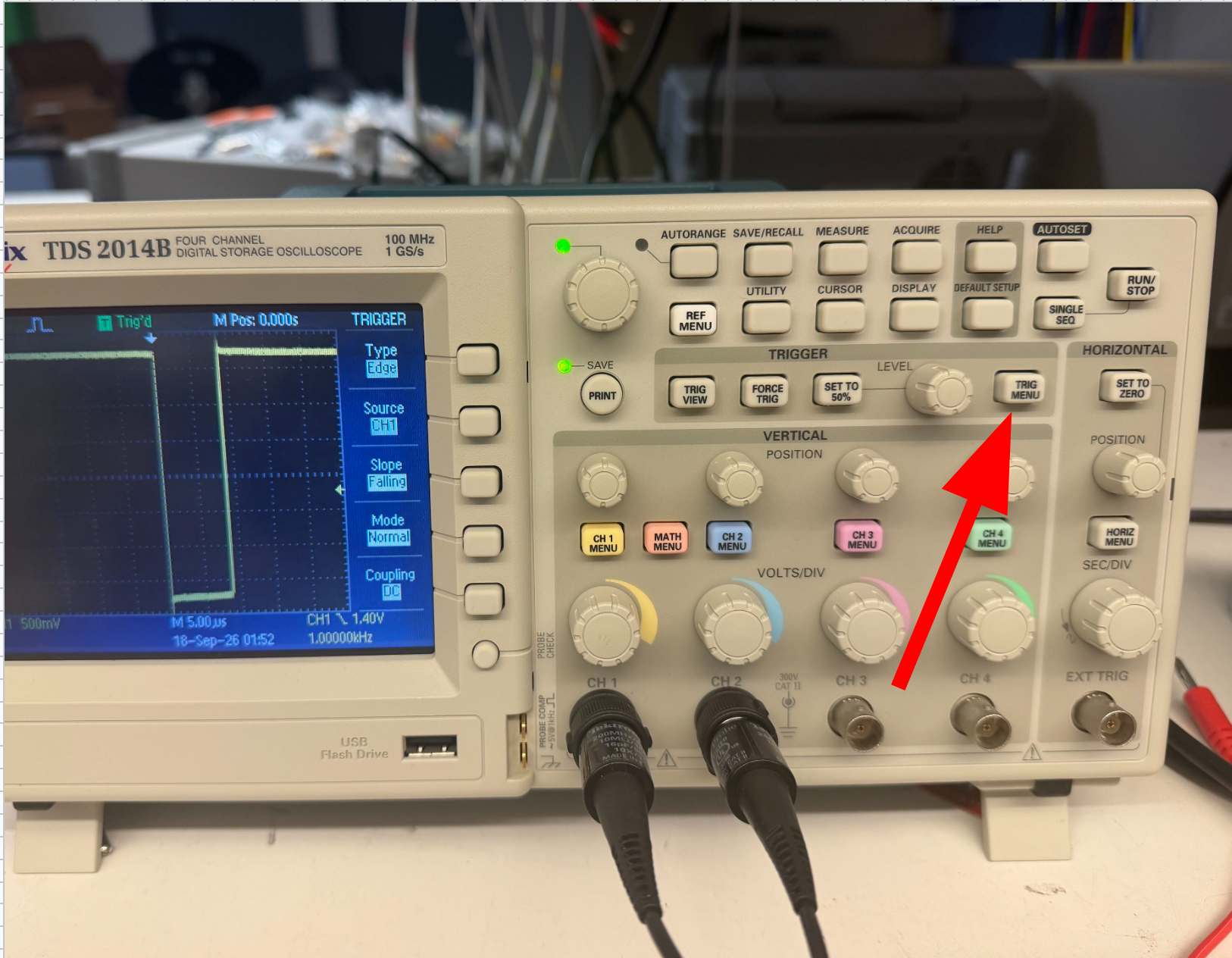
Trigger modes — how the scope behaves while waiting:
- Auto — updates the screen whether or not the trigger condition is met.
- Normal — only updates the screen when the condition is met, and holds the last capture in between trigger events.
- Single — waits for our trigger condition to be met, updates the screen once, then stops, and just displays that(you prob won't use this but no hurt in knowing what it is).
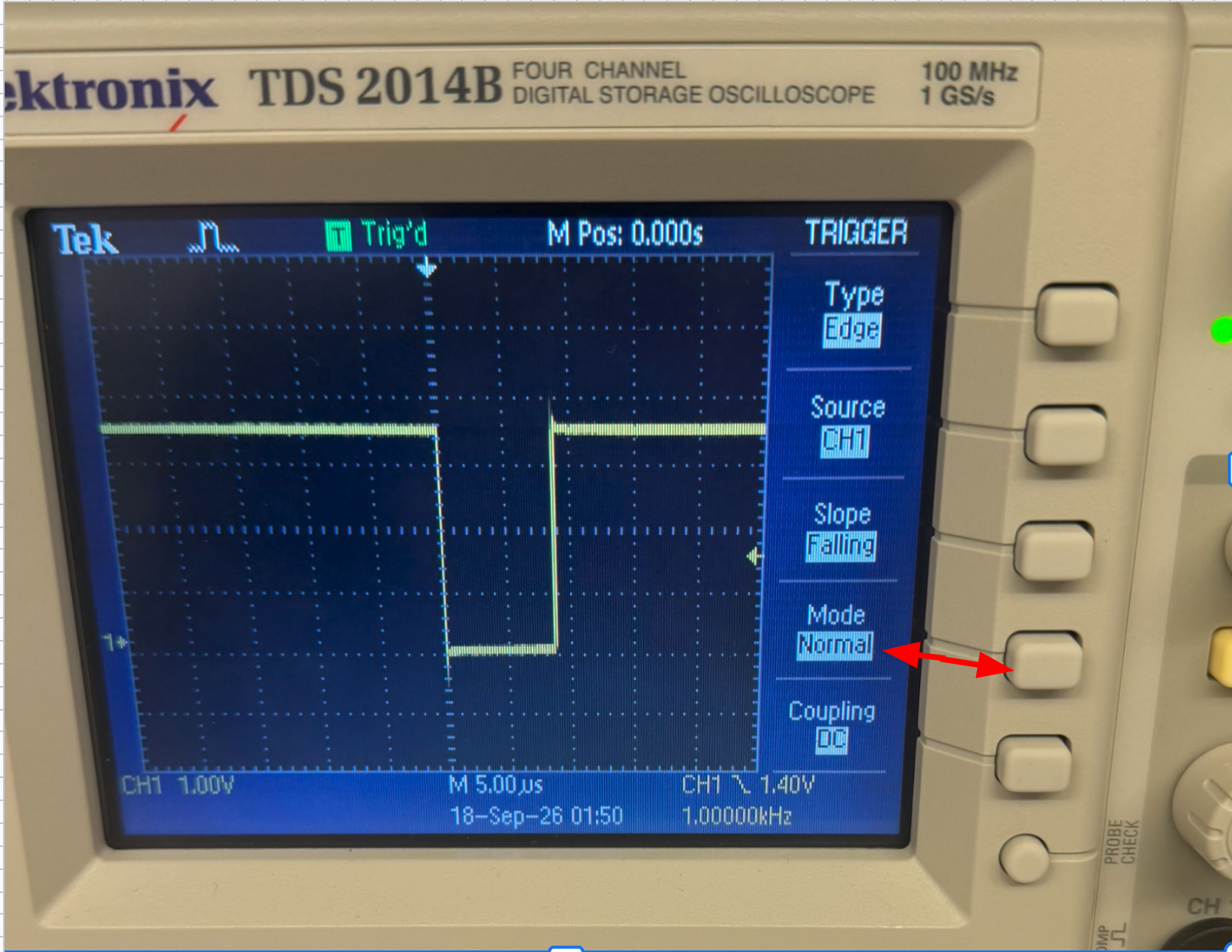
Trigger events — the condition the scope is looking for I think for most cases in this class we'll use Edge, so just set it to Edge. Now there are different Edge types,which on our scopes are changed by the slope field, their kinda self explanatory but
- Rising Edge — an event is when when it detects the signal change from low to high
- FallingEdge — an event is when it detects the signal change from low to high
Trigger threshold — the voltage the signal has to cross to count as an event.