LED RGB Controller
The Whole Avocado
Please Log In for full access to the web site.
Note that this link will take you to an external site (https://shimmer.mit.edu) to authenticate, and then you will be redirected back to this page.
In the previous few assignments you developed a basic counter, a device which increments its output over time. We also added a cycle-limit on it so we don't have to rely on the natural overflow of a fixed number of bits. A simple module like this is extremely versatile and can enable us to do many things.
For the final portion of this week's work, you're going to develop a LED color controller. This will be a sequential circuit that builds upon your counter module from the previous pages. It will use the sixteen bits of the slide switches on your development board to control the brightness of the red, green, and blue channels of the RGB LED also on your board. The sixteen bits of the switches will be split and used such that:
- The five bits of
sw[15:11]control the red brightness ranging from 0% to ~100% in approximately equidistant steps. - The six bits of
sw[10:5]control the green brightness ranging from 0% to ~100% in approximately equidistant steps. - The five bits of
sw[4:0]control the blue brightness ranging from 0% to ~100% in approximately equidistant steps.
This color configuration is known as "565" from the number of bits assigned to each color channel, and it is very common in size in resource-restricted devices. Historically since 16 bits was a common clean fraction or multiple of the word size of many architectures, it was very widely used. The choice of having the green channel get twice the resolution of red or blue comes from the fact that the human eye has more relative sensitivity to green than red or blue in trichromatic vision.
We will explore color space and its variants more in future weeks, but for now we'll just focus on Red Green Blue (RGB).
In your top_level.xdc file, there are six lines that pertain to two onboard RGB LEDs called rgb0 and rgb1. Each "LED" is actually three LEDs in one package. They are wired up in the following fashion known as "common cathode":

You should have previously uncommented lines in your .xdc file that correspond to rgb0 and rgb1, as shown below. In the initial version of top_level.sv, we set both of these RGB LEDs to 0, but now we'd like to control RGB0 with a module we're about to implement (keep RGB1 pulled to 0 to avoid needless visual distractions).
set_property -dict {PACKAGE_PIN C9 IOSTANDARD LVCMOS33} [get_ports {rgb0[0]}];
set_property -dict {PACKAGE_PIN A9 IOSTANDARD LVCMOS33} [get_ports {rgb0[1]}];
set_property -dict {PACKAGE_PIN A10 IOSTANDARD LVCMOS33} [get_ports {rgb0[2]}];
set_property -dict {PACKAGE_PIN A11 IOSTANDARD LVCMOS33} [get_ports {rgb1[0]}];
set_property -dict {PACKAGE_PIN C10 IOSTANDARD LVCMOS33} [get_ports {rgb1[1]}];
set_property -dict {PACKAGE_PIN B11 IOSTANDARD LVCMOS33} [get_ports {rgb1[2]}];
We shall keep rgb1 set at 0, but remove the line that is setting rgb0 to always be 0. Instead, in your top_level.sv add in an instance of a yet-to-be-defined module rgb_controller that is wired into your overall design like shown:

The module you're building will control the brightness on the three channels. But...how...could it do that? The pins r_out, g_out, and b_out are all one bit in size and can therefore either just be on or off (nothing in between). We want "shades of grey" for each color channel however. At face value this seems to necessitate the ability to create analog signals (signals that can vary from 0 to 1 in many small sub-steps), but we don't have that. It seems we're at an impasse. Maybe one day we'll figure it out. Please turn in your 6.205 board. You've reached the end of the field of digital design.
Just joking! We can fix the problem at hand by using the very high speeds of our digital devices to kinda sorta fake it.
Pulse Width Modulation
Pulse Width Modulation is way to encode an analog signal using a one bit digital value that turns on and off periodically but at different on/off ratios. The amount of "on" time relative to the full time of a single period is known as the Duty Cycle.
By varying the duty cycle you can encode different analog values. The higher the duty cycle, the higher the analog value encoded. The lower the duty cycle, the lower the analog value conveyed. This encoding scheme is particularly useful because you can run it through a regular analog low-pass filter to extract the analog value (effectively get the average of the signal). This could be an electronic circuit or it could even just be something more "organic" like human eyeballs. As humans, our vision lacks the ability to see flashing above several hundred Hz in frequency. As a result, if you flash a light on and off at a frequency above this "cutoff" at varying duty cycles using a PWM scheme, we end up seeing varying levels of brightnesses and not the flashing part. This isn't just hand-wavyness either. We won't do it here, but if you do the Fourier Transform of various PWM signals and run them through filters, the low-frequency components will vary in intensity.

Binary Concerns
We'd like to implement a PWM signal using System/Verilog. We need to think about this in terms of bits. Notice above that values can be conveniently encoded in binary. In the example, we're using four bits to describe the space of possibility.

For a given number of bits n, you'll always have 2^{n} possibilities, but we'll need to use them to express our entire range for a PWM duty cycle, fully-off to fully-on (inclusive).
An implementation of a PWM module using the counter module you already developed here is shown below. The new signal dc_in is the duty cycle specification. Amazingly, a simple threshold comparison of count with dc_in can generate the patterns shown above.
module pwm(   input wire clk,
              input wire rst,
              input wire [3:0] dc_in,
              output logic sig_out);

    logic [31:0] count;
    counter mc (.clk(clk),
                .rst(rst),
                .period(15),
                .count(count));
    assign sig_out = count<dc_in; //very simple threshold check
endmodule
Very Cool.
More Bits
The module above only has four bits worth of duty cycle that it can specify. That's only sixteen brightness levels as you've already determined up above. We'd actually like to have more resolution than this. Human visual perception is usually about ~200 or so levels in the red, green, and blue channels. In order to achieve this we need our duty cycle to be specified with more than 4 bits.
In adding more bits to our duty cycle, an unintended consequence is that the period of our wave will also go up because we can only make a decision on each clock cycle. Generalizing this out a bit more, if we instead used more bits to encode our PWM duty cycle, n, we'll get the ability to express more shades of grey. In order to express this increase in duty cycle possibilities, we'll need our period to become larger.
For our specific situation with 8 bits, what will the PWM period be?
Even with more bits, and a lower frequency, the PWM signal is still in the 100's of kHz, much higher than what can be perceived by a human eye, so the illusion of differing brightnesses can still hold.
Your Assignment
As your final assignment for this week, you should modify the pwm module to support 8 bit duty cycles. Then use three of the pwm modules in building the module rgb_controller shown in Figure 2. Be sure to make separate files for pwm (pwm.sv) and the rgb_controller (rgb_controller.sv)
Part 1: Simulation
For your development, here's a very simple cocotb testbench that you can use for verification of some waveforms of the rgb_controller, place it in your sim file and name it test_rgb_controller.py, then run the simulation. As a reminder, the waveform will file will appear as an .fst in the sim_build directory that appears. View that with any waveform viewer we suggested.
import cocotb
import os
import random
import sys
import logging
from pathlib import Path
from cocotb.triggers import Timer
from cocotb.utils import get_sim_time as gst
from cocotb.runner import get_runner
test_file = os.path.basename(__file__).replace(".py","")

async def generate_clock(clock_wire):
	while True: # repeat forever
		clock_wire.value = 0
		await Timer(5,units="ns")
		clock_wire.value = 1
		await Timer(5,units="ns")

@cocotb.test()
async def first_test(dut):
    """First cocotb test?"""
    await cocotb.start( generate_clock( dut.clk ) ) #launches clock
    dut.rst.value = 1;
    dut.r_in.value = 100
    dut.g_in.value = 10
    dut.b_in.value = 220
    await Timer(20, "ns")
    dut.rst.value = 0; #rst is off...let it run
    await Timer(100000, "ns")# run for many cycles

"""the code below here should largely remain unchanged in structure, though the specific files and things
specified will get updated for different simulations.
"""
def rgb_runner():
    """Simulate the counter using the Python runner."""
    hdl_toplevel_lang = os.getenv("HDL_TOPLEVEL_LANG", "verilog")
    sim = os.getenv("SIM", "icarus")
    proj_path = Path(__file__).resolve().parent.parent
    sys.path.append(str(proj_path / "sim" / "model"))
    sources = [proj_path / "hdl" / "rgb_controller.sv"] #grow/modify this as needed.
    sources += [proj_path / "hdl" / "counter.sv"] #grow/modify this as needed.
    sources += [proj_path / "hdl" / "pwm.sv"] #grow/modify this as needed.
    hdl_toplevel="rgb_controller"
    build_test_args = ["-Wall"]#,"COCOTB_RESOLVE_X=ZEROS"]
    parameters = {}
    sys.path.append(str(proj_path / "sim"))
    runner = get_runner(sim)
    runner.build(
        sources=sources,
        hdl_toplevel=hdl_toplevel,
        always=True,
        build_args=build_test_args,
        parameters=parameters,
        timescale = ('1ns','1ps'),
        waves=True
    )
    run_test_args = []
    runner.test(
        hdl_toplevel=hdl_toplevel,
        test_module=test_file,
        test_args=run_test_args,
        waves=True
    )

if __name__ == "__main__":
    rgb_runner()
We want 8 bits of resolution on each color channel even though we'll only use the top 5, 6, and 5 bits for red, green, and blue, respectively for now (next week we'll be using all 8 bits).
An important part of your PWM module (and one which will be important when we use it for audio), is that we do not want to be able to instantly (either through combinational-only logic or a single flip-flop) control the output signal by arbitrarily changing various values of r_in, g_in, and b_in. Instead we only want the module to change its PWM duty cycles when the the cycle is about to return to 0. What this means is that regardless of when you change values for r_in, g_in, and b_in, the duty cycle should only change after the current cycle has complete. It would be quite hard to force a user to only flip switches when the PWM modules are at their max counts (an event lasting only 10 ns)...so another more robust way of saying this is, the system should only "grab" the input brightness levels right before the PWM counter resets back to zero.
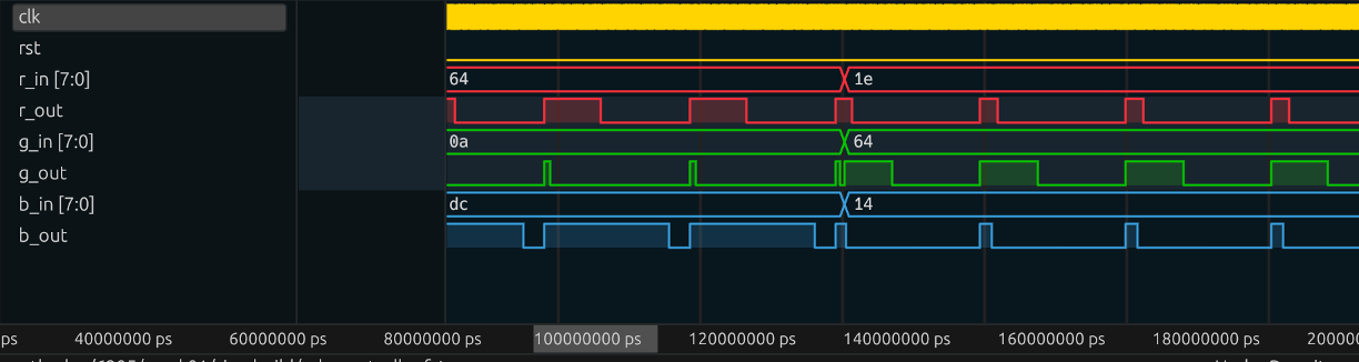
The reason for this is we want to avoid changeover issues where the PWM signal is neither the old, nor the new value, but instead something else that isn't even in between and which varies in frequency. Look at the Green signal (g_in and g_out) below. The duty cycle changes from 0x0a (15/255) to 0x64 (100/255) and g_out does that weird high-low-high transition that is:
- A: higher instantaneous frequency than our fixed PWM frequency and
- B: some weird abomination of duty cycle.
The red signal doesn't look too bad (through sheer luck), but it is still the wrong frequency, and the blue signal also looks kinda wrong for a brief cycle.
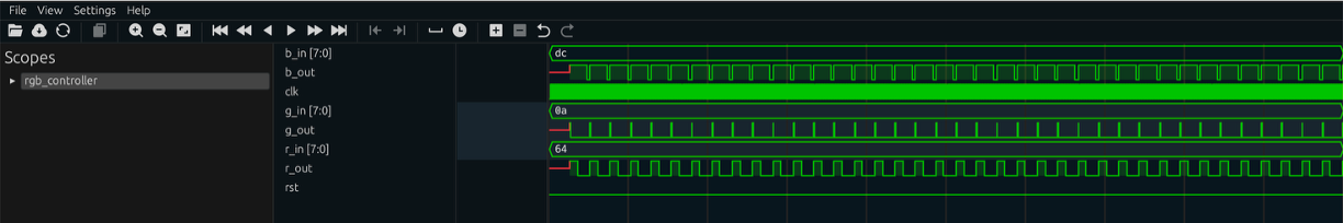
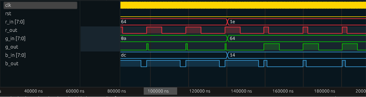
Instead you only want your PWM behavior to transition at the point of reset as shown below. Look at the three waveforms below. Even though the command duty cycles change at the same point, the three PWM signals finish the count cycle they're on before adjusting, thus maintaining a constant frequency signal and presenting no messed up temporary duty cycles.
The easiest way to implement this will be in the PWM module itself and not the outer rgb_controller module.
Make sure your waveform and cocotb simulation are clearly showing:
- Different input values and the correct output behavior on all three channels of the
rgb_controllermodule. - Correct transitions between different duty cycles as discussed above.
When your simulation is acting roughly as expected, integrate the module into your project.
Part 2: Integration
Note that we need a clock for our sequential logic. We will be using the 100 MHz clock integrated in the Urbana board. Uncomment both lines pertaining to clk_100mhz in the xdc file, and add an input wire to the top_level.sv with the same name. Now we can pass the 100 MHz clock into all our modules!
Now, build and celebrate your design with different colors. You should have something that looks similar to the video below:
Part 3: Logic Analyzer Analysis and Verification
Finally, how do we really know that our PWM is working? Yeah our eyes are detecting differences in brightness, but we can't actually see the PWM signal. We need something that can do that for us. An oscilloscope would be good, but overkill. Instead we can use a device that is like an oscilloscope but only for digital signals: the logic analyzer.
We'll break out these PWM signals on a few of the "PMOD" pins on the side of your FPGA board. PMOD stands for "Peripheral Module" and there are a bunch of modules designed to plug into that port. For now we'll just activate three of the pins and use them as outputs with some wires to view the three PWM signals for R, G, and B. In later weeks we'll have fancy-schmancy things to plug in.
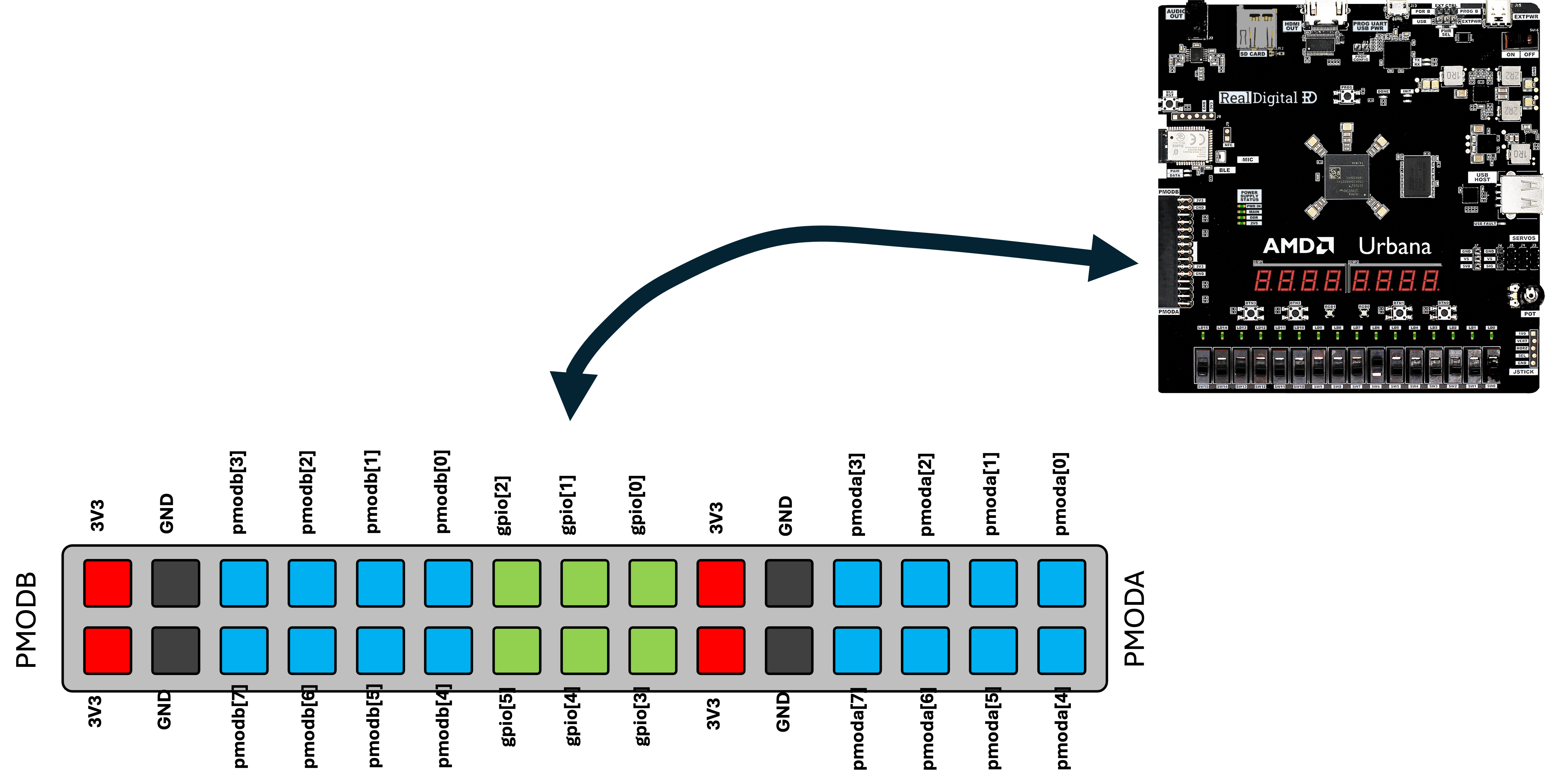
Go back to your XDC file and uncomment the three set_property lines below:
# PMOD A Signals

#set_property -dict {PACKAGE_PIN F14 IOSTANDARD LVCMOS33}  [ get_ports "pmoda[0]" ]
#set_property -dict {PACKAGE_PIN F15 IOSTANDARD LVCMOS33}  [ get_ports "pmoda[1]" ]
#set_property -dict {PACKAGE_PIN H13 IOSTANDARD LVCMOS33}  [ get_ports "pmoda[2]" ]
Then go to your top_level module and add a 3-bit output logic matching the name of those pins (pmoda). Link your three PWM signals for red, green, and blue PWM signals, respectively. Finally run a new build and program your FPGA with it.
We're now going to hook up the logic analyzer that came in your kit. If you haven't already set this device or software (Pulseview) up, go to the documentation page for it.
Using some of the rainbow wires at the front of the lab space (you just need four), connect:
Be careful to only plug int GND to GND. If you connect it into 3.3V accidentally you may short out your FPGA and/or USB port
- Logic Analyzer GND to PMOD GND (pay careful attention to and make sure you're plugging into ground and not 3.3V. Seriously count the pins!!!)
- Logic Analyzer CH0, CH1,CH2 to
pmoda[0],pmoda[1],pmoda[2], respectively.
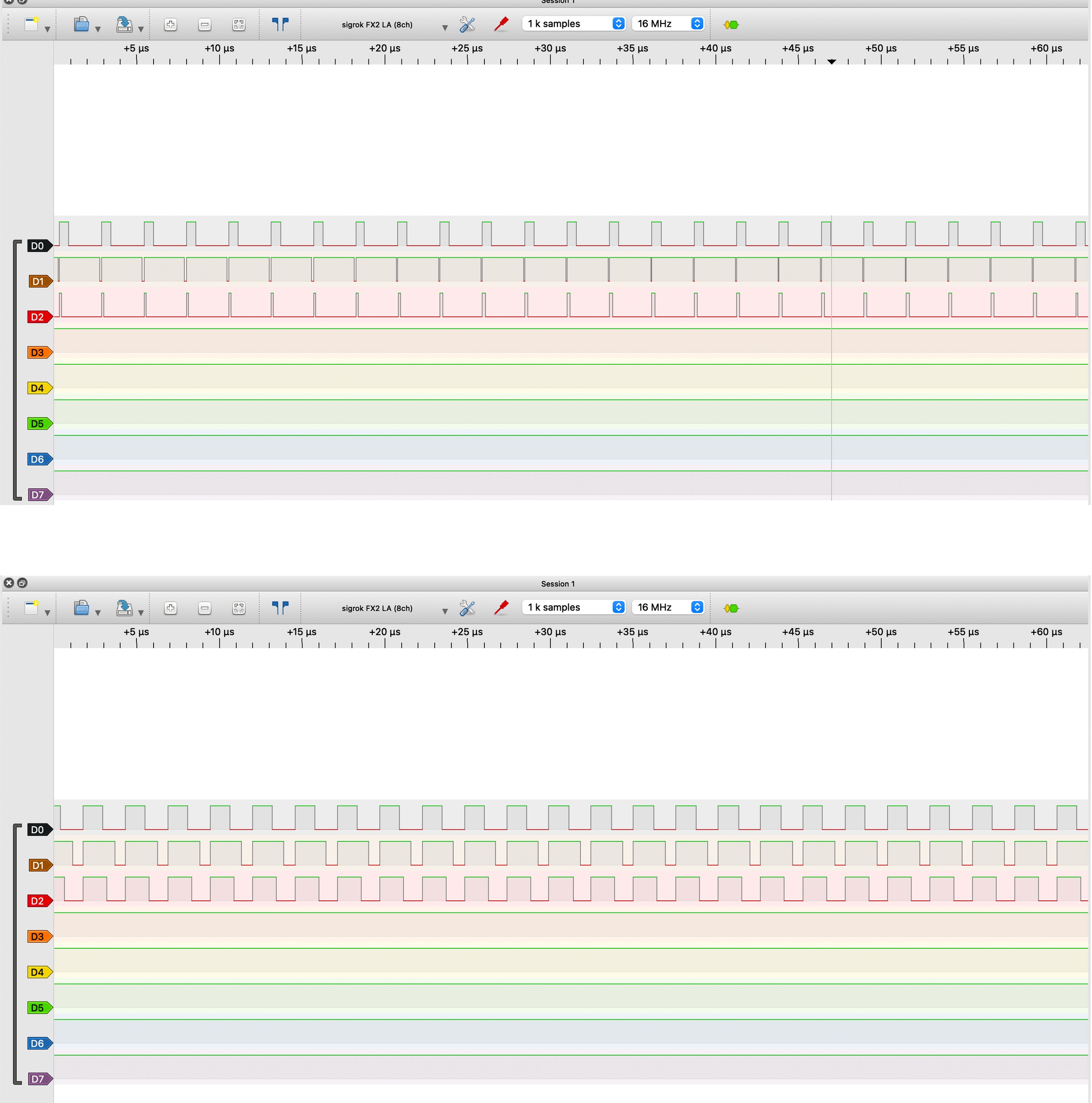
Set things up to grab 1,000 samples at 16 MHz. Do some free-run captures (no need for a trigger since the signal is always running) until hopefully you're seeing some signals showing up. When you've done it correctly, you should be able to see your three PWM signals and varying duty cycles as you change the levels. The figure below has two example captures off my board at different PWM rates.
When everything is ready, you can ask for the checkoff below. In order to get the checkoff you need to do all of these things (it is a logical AND operation not an OR operation).
- A functioning testbench and waveform showing your RGB module at different duty cycles and importantly correctly transitioning between different duty cycle values
- Your working overall LED brightness system working
- Your logic analyzer hooked up and showing the logic analyzer measurements showing different PWM duty cycles. Use the cursors in software to measure the period and frequency of your PWM signal. How does it compare to what you predicted earlier on this page?
If the staff member shows up and you do not have all of these things ready, they are not going to give you a checkoff. It is not their job to sit with you while you bring these things up so make sure you're prepared when you ask for the checkoff!
For checkoff 3, show some waveforms of a working PWM module at a few different duty cycles and make sure to show your PWM signals transition cleanly from one value to another. Then show your RGB controller working based on the 16 switches. Be prepared to show the staff member how you wired up your entire design and explain any major decisions you made. Finally use your logic analyzer to show actual real-life PWM signals of varying duty cycles and measure the frequency of the PWM signal.