Please Log In for full access to the web site.
Note that this link will take you to an external site (https://shimmer.mit.edu) to authenticate, and then you will be redirected back to this page.
For this lab we're going to do several things:
- Create a project from scratch.
- Build a few test platforms that we want to analyze (an integer division setup and a float operation).
- Use an interfacing library to test the system (by analyzing its inputs and outputs).
Your build.py can be the same as Lab07. For a build.tcl you can use this one here.
This project is similar to other ones, but (time to leave the nest, baby bird) you'll need to create all the files from scratch 1
Your top level module should have the following inputs and outputs:
- input
clk_100mhz - input
[15:0] sw - output
[15:0] led - output
uart_txd - input
uart_rxd
For your XDC file, start with a copy from another lab. Then comment out anything not being used by your design. In addition, we've never used uart_rxd or uart_txd before. To link them to the FPGA pins you'll need to add the following to your xdc file:
# uart pins for working with manta:
set_property PACKAGE_PIN B16 [ get_ports "uart_rxd"]
set_property PACKAGE_PIN A16 [ get_ports "uart_txd"]
set_property IOSTANDARD LVCMOS33 [ get_ports "uart*"]
For this first part, we'll be testing our integer division in hardware. Bring over the divider module from lab05 and include it with this project's source. After that you should be all set for the next part.
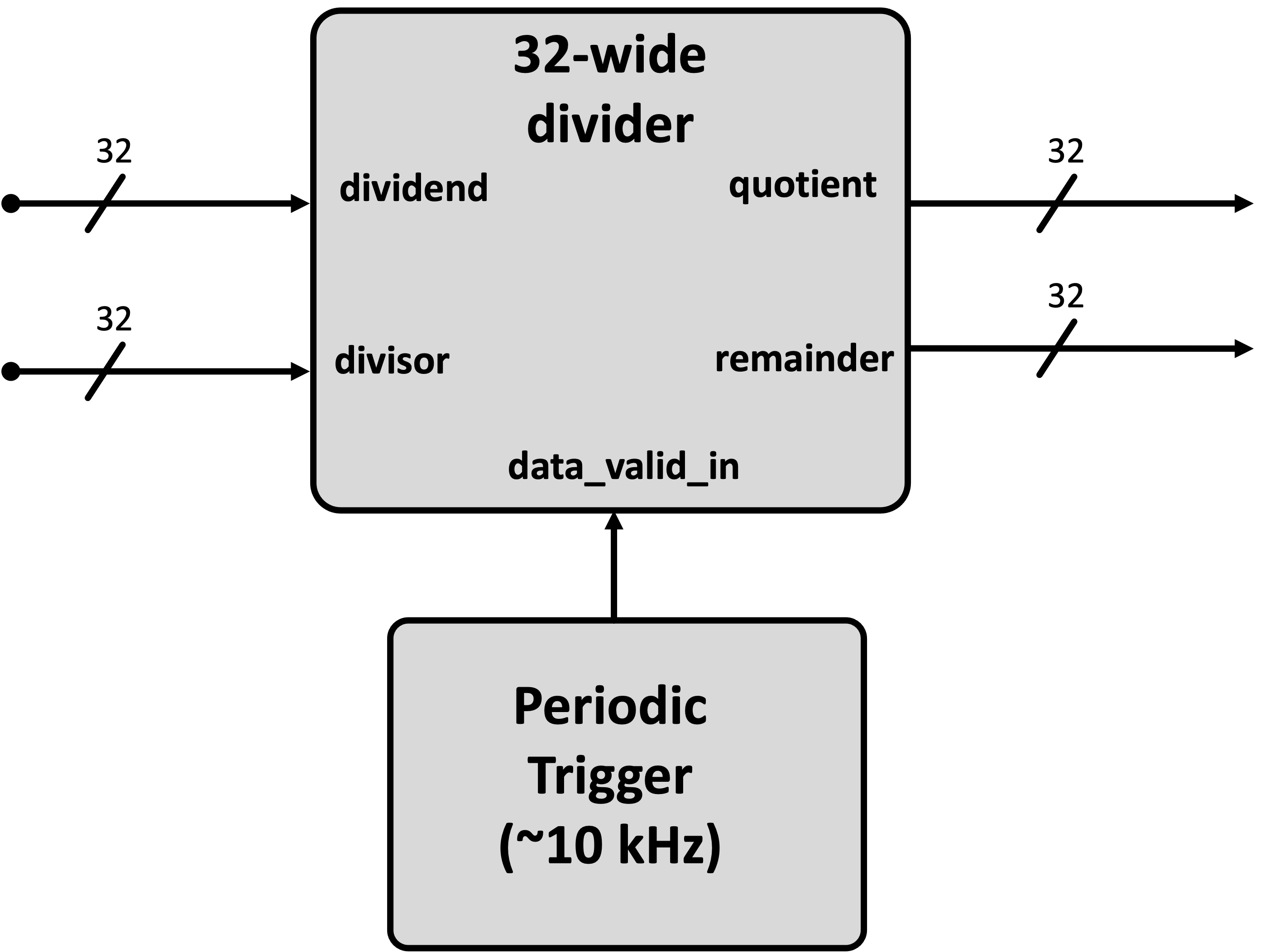
The first thing we want to do is build a system that takes two 32 bit numbers and runs a 32 bit version of the divider from class. That system should run a division periodically at about a rate of 10 kHz regardless of what the inputs are (therefore you should trigger division with a single-cycle enable signal at a rate of 10 kHz)2. Roughly speaking, your code should look like this below (although we're not drawing a few different signals that are needed for the sake of simplicity).
How will we get values into and out of this divider? Well we could use the switches, and then read the values out of the LEDs...but like that's annoying. Is there a better way? Yes.
What we'd next like to do is actually be able to study the signals that this module generates on the hardware. This is different than a simulation...we actually want to set and record the actual values going into and out of a module running in real life.
Xilinx has something to do this and it is actually pretty good, but you have to use the Vivado GUI for it and we'll avoid that.
An alternative was written last year by a former 6.205 TA, Fischer Moseley. He's currently at JPL, but this was his M.Eng thesis last year. The project is Manta which is an open-source debugging/interface for FPGAs that can help us in analyzing and working with our designs. He spent some time writing some docs which are here. You should read through them.
In general what this project does is allow you to create a System-Verilog-based module that can live on your FPGA that can then also interact with your computer (over serial). You can use this to both exchange information between your computer and the FPGA as well as measure internal signals. While absolutely no replaced for rigorous simulation-based testing of your designs, the features this provides can help in a lot of final-stage debugging steps. The Manta project offers a number of functionalities, but we'll look at just one of them today (the IO Core), though the logic analyzer and others may also be useful in your final projects.
So go to the docs page for Manta and follow the install instructions. Should be pretty easy...since it uses pip. I'd recommend installing on a python virtual environment if possible rather than your system Python if possible.
So in Manta we create modules that we can control over Python but which "live" in the FPGA. In order to make this work, requires the creation of both RTL and Python constructs that understand eachother (the foundation of any good communication system). In order to facilitate this, Manta uses yaml files to describe what you want to build. You then have manta generate a System Verilog module that performs the tasks we want. You put that System Verilog module in your FPGA project, build it, program the FPGA, and then you run Manta on your computer (referencing the same yaml file) to talk to your FPGA in real-ish time3
Consider the yaml file below that we'll use in this lab. It generates a SystemVerilog module that will enable us to (via Python):
- read in two 32 bit values from your FPGA (
val1_inandval2_in) and - set or control two 32 bit values on your FPGA (
val3_outandval4_out)
---
cores:

  lab8_io_core:
    type: io

    inputs:
      val1_in: 32
      val2_in: 32

    outputs:
      val3_out: 32
      val4_out: 32
uart:
  port: "/dev/cu.usbserial-6"
  baudrate: 3000000
  clock_freq: 100000000
This yaml file can be used largely as is, however you will likely have to change the name that is on the port field. This value will vary depending on your machine and even which particular FPGA board you're using. There is an "auto" option you can put there, but it doesn't seem to work very reliably with these boards.
Instead what you should do is with your FPGA plugged in to your computer, run:
manta ports
A list of ports should come back. One of these should work, though we may need to do a little debugging on certain computers. When it gets time to run things, you may need to jump back to this and update the yaml a few times with different ports before we can see if it is working or not.
Anyways we can figure out the port in a little bit. For right now, let's generate the .sv file from .yaml. With Manta installed you should be able to do:
manta gen lab08.yaml hdl/manta.sv
This will generate a System Verilog module contained in manta.sv of this rough shape:
module manta (
    input wire clk,

    input wire rx,
    output reg tx,

    input wire [31:0] val1_in,
    input wire [31:0] val2_in,
    output reg [31:0] val3_out,
    output reg [31:0] val4_out);
  //lots of stuff
endmodule
You should be able to find the module in the hdl folder of your project.
At the top of the file, you'll see an example instantiation provided. Feel free to use that to integrate it into your top_level module. We now want to use it so that it is integrated into your design allowing us to test the divider module. Build the system as shown below:
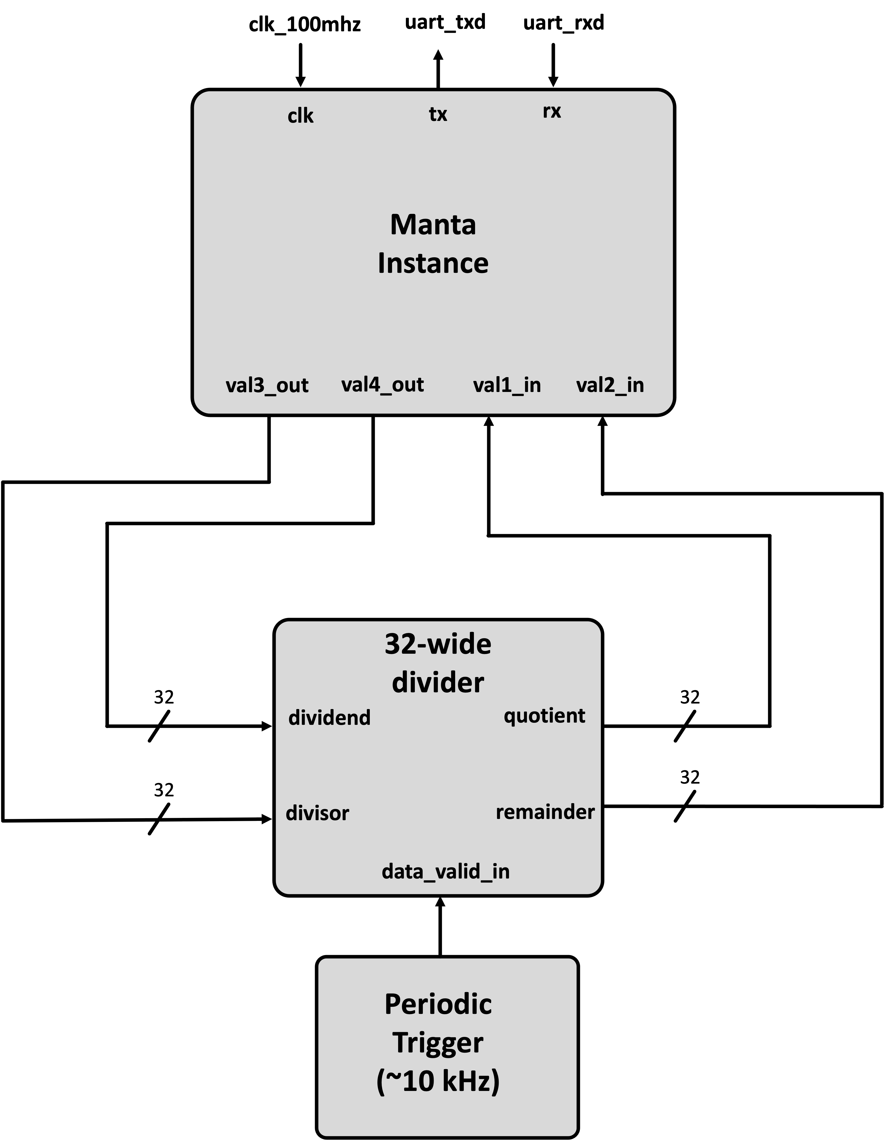
When you feel like you've gotten this working it is time to check to see if you have it set up. Run a build. And then program your FPGA like usual.
Now let's write some Python using the manta package to interface with the FPGA. Consider this code below:
import time
from manta import Manta
m = Manta('lab08.yaml') # create manta python instance using yaml

val3 = 11
val4 = 9101
m.lab8_io_core.val3_out.set(val3) # set the value val3_out to be val3
m.lab8_io_core.val4_out.set(val4) # set the value val4_out to be val4
time.sleep(0.01) # wait a little amount...though honestly this is isn't needed since Python is slow.
a = m.lab8_io_core.val1_in.get() # read in the output from our divider
b = m.lab8_io_core.val2_in.get() # read in the output from our divider
print(f"Values in were {val3} and {val4} with results {val4}//{val3}={val4//val3} and {val4}%{val3}={val4%val3}.")
print(f"Actual results were: {a} and {b}!")
This code does a few things:
- sets up a Manta instance
- sets some values which get piped down to the FPGA.
- reads some values from the FPGA
- compares them to what we expected.
A working system when run will provide a result like this (using the code above):
Values in were 11 and 9101 with results 9101//11=827 and 9101%11=4.
Actual results were: 827 and 4!
Make sure are getting something like that. When you do, expand the python script above so that you test and compare the division functionality on ten input values! When done, ask for a checkoff.
When done show this to a staff member! Explain what is going on!

OK keep everything as it was before. (nothing needs to be deleted en masse). We're just going to "add on" to the system.
We'd now like to build a non-trivial floating point math pipeline. This system takes in two IEEE 754 32 bit floats, the encoding of which we mentioned in lecture 11, and then performs math operations on them. Specifically if our two input floats are x and y, it will calculate z as the following:
Research up how floating point works and write some algorithms to do this. JKJK L.O.L. We're always laughing, you and me. It's great, right? In another week, we would do this, but this is a short lab and instead we'd like to use this as an opportunity to get experience working IP modules. These are customizable modules you can create from within Vivado that perform certain tasks. Most Xilinx IP communicates (takes in data and hands data out) using the AXI streaming protocol (see lecture 10) so make sure you review that.
How do you "get" IP? Well we'll use the Vivado GUI. If you have Vivado actually installed, just open it up by running vivado (or maybe clicking a link if you made one). If you are using Vivado remotely through the terminal you'll need to instead use one of the lab computers. Go to one of the lab computers that has Ubuntu installed (computers 31 and up), log in using your MIT kerberos/username. Your password will be "fpga_" + your nine-digit MIT id. So if you MIT ID is 123456789 you'd do "fpga_123456789". Once logged in you'll be in Ubuntu.
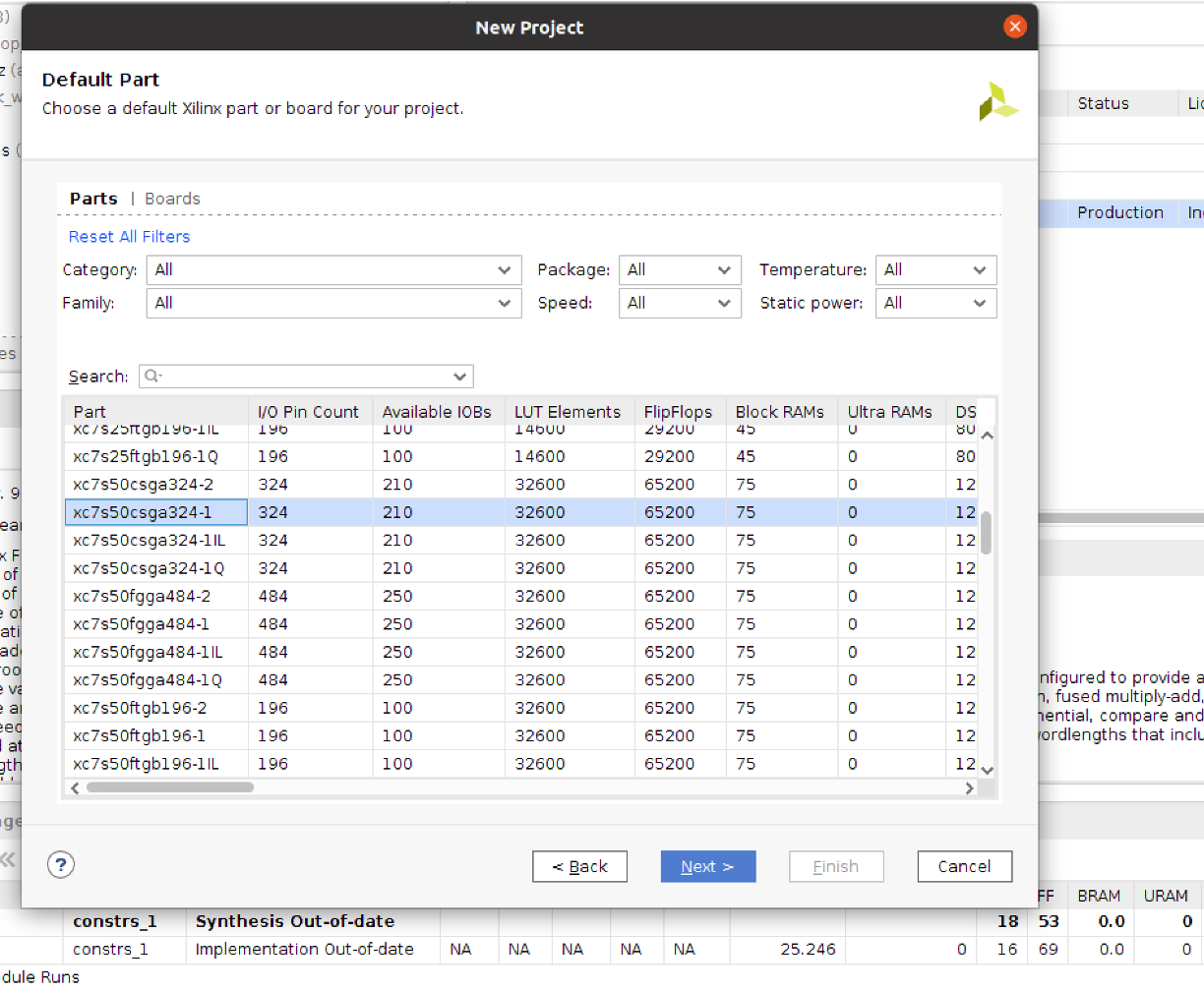
Open up a terminal and run vivado. This will launch the Vivado GUI. Once it comes up it'll ask if you want to make a new project. Say yes. Name it whatever. I don't care (don't put spaces in it though). Choose it to be a RTL Project. Click through the next few steps (no need to add any sources or constraints). When you get to the step where it prompts you for what type of FPGA or board (the "default part") you're using (see figure below), target the xc7s50csga324-1 part (this is important).
Click Next until you're done and you'll find yourself in a Vivado project's home.
We're not going to actually build anything here. Some of you may end up in here during final projects but that day has not yet come. Instead we're just going to use the GUI to customize some IP modules for us4. We'll then grab the files it generates, and bingo bango bongo, we'll get out of here and back to our regular framework.
On the left side of the Vivado environment, there is an IP catalog button. Click on it and then when that comes up search for "float". One option should come up making floating point IP. Click on it. This will bring up a window that let's you create a customized IP module that performs a particular operation.
You need to make three different IP modules. Specifically you'll need to make a:
- 32 bit floating point adder (takes in two 32 bit floats and generates one 32 bit float)
- 32 bit floating point multiplier (takes in two 32 bit floats and generates one 32 bit float)
- 32 bit floating point inverse square rooter (takes in one 32 bit float and generates one 32 bit float)
Make the adder first. Select the adder option and make sure it just adds...that'll keep the interface simpler. Call this module "adder" (in the top component name field). We can use the default options otherwise. When you're making it, make sure to take a photo or something of all the interfaces and things that it shows on the left side (an example of mine is shown below). This will be helpful for debugging.
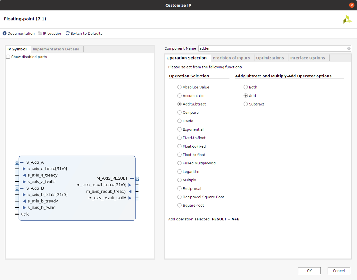
When ready click ok/build and give it a little bit. There will likely be a window that pops up saying something about generating Out of Context Products. That's fine. Click ok with the default options it gives.

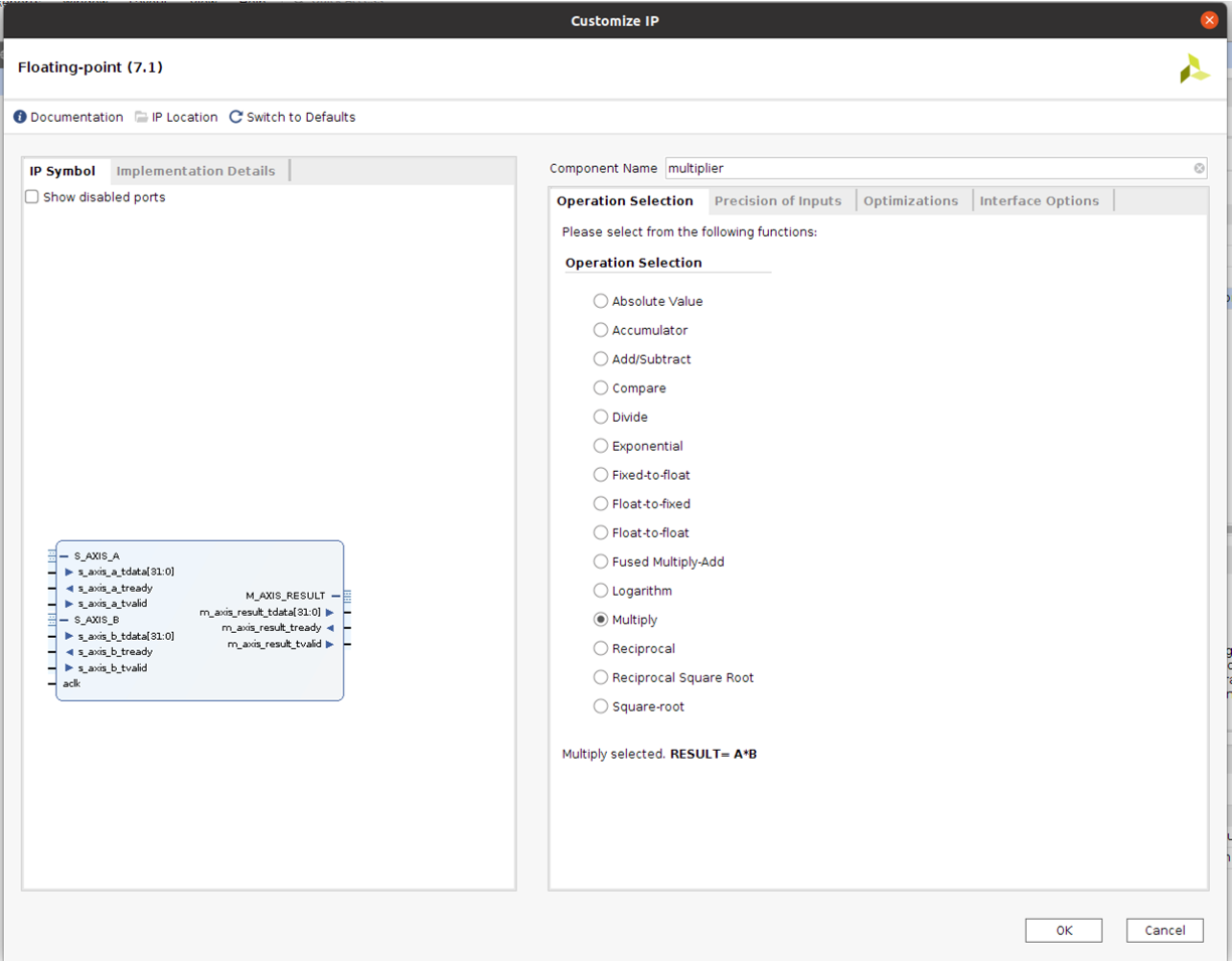
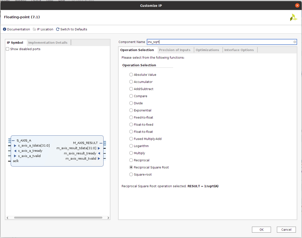
After it is all done and made the floating point adder, now make the other two modules. A 32 bit multiplier and a 32 bit inverse square rooter. Call these whatever you want (I used 'multiplier' and 'inv_sqrt'). Do the same thing and basically use the default options the IP wizard provides. Make notes of their inputs and outputs (take photos or screenshots of yours so you have a reference in case something doesn't work).
Now that you've generated your IP, you need to get to it. The files we care about are called .xci file and each IP has one. Find the folder you made for this project (probably called "project_1" in your home directory if you just used the defaults). In that folder go into project_1.srcs. In there will be a folder called sources_1 or something and in there will be a folder called ip. That's the one we want. Inside it will be three folders...one for each IP module you made. Each one of those folders has an .xci file in it.
Make a zip or compressed version of the entire ip folder and transfer it to your local computer (use scp or ssh or whatever. All computers in the lab have static IP's so if you're on eecs-digital-43.mit.edu for example you can scp the zipped folder from this computer to your local machine easily.
Assuming you made the IP correctly, you should be all good to go and can log out of that lab computer.
Once that IP folder is on your computer where you're normally doing your builds, decompress it and then move a copy into your project for this lab. Make sure to keep the general structure of the folder, though, so have the following (Vivado likes to keep IP files separate):
ip-->+
     |
     adder-->+adder.xci
     |
     multiplier-->multiplier.xci
     |
     inv_sqrt-->inv_sqrt.xci
Before we can use it we need to change a few more things.
In each .xci file you need to change the file path in two spots. The two spots are the "gen_directory" and the "OUTPUTDIR" lines. Change the file paths there so they are the appropriate relative locations for your project. For example, changing my inv_sqrt spots I did:
"gen_directory": "./ip/inv_sqrt"or whatever you named your IP"OUTPUTDIR": [ { "value": "./ip/inv_sqrt" } ],
Do that for all three .xci files. then once done, you're all set to use them.
Also before we forget, update your build.tcl with this updated version found here that will include IP modules. This script is dependent on file names, however so go into it and make sure the following lines referencing your IP modules match what you called your IP modules.
# Read in all IP
read_ip ./ip/multiplier/multiplier.xci
read_ip ./ip/adder/adder.xci
read_ip ./ip/inv_sqrt/inv_sqrt.xci
generate_target all [get_ips]
synth_ip [get_ips]
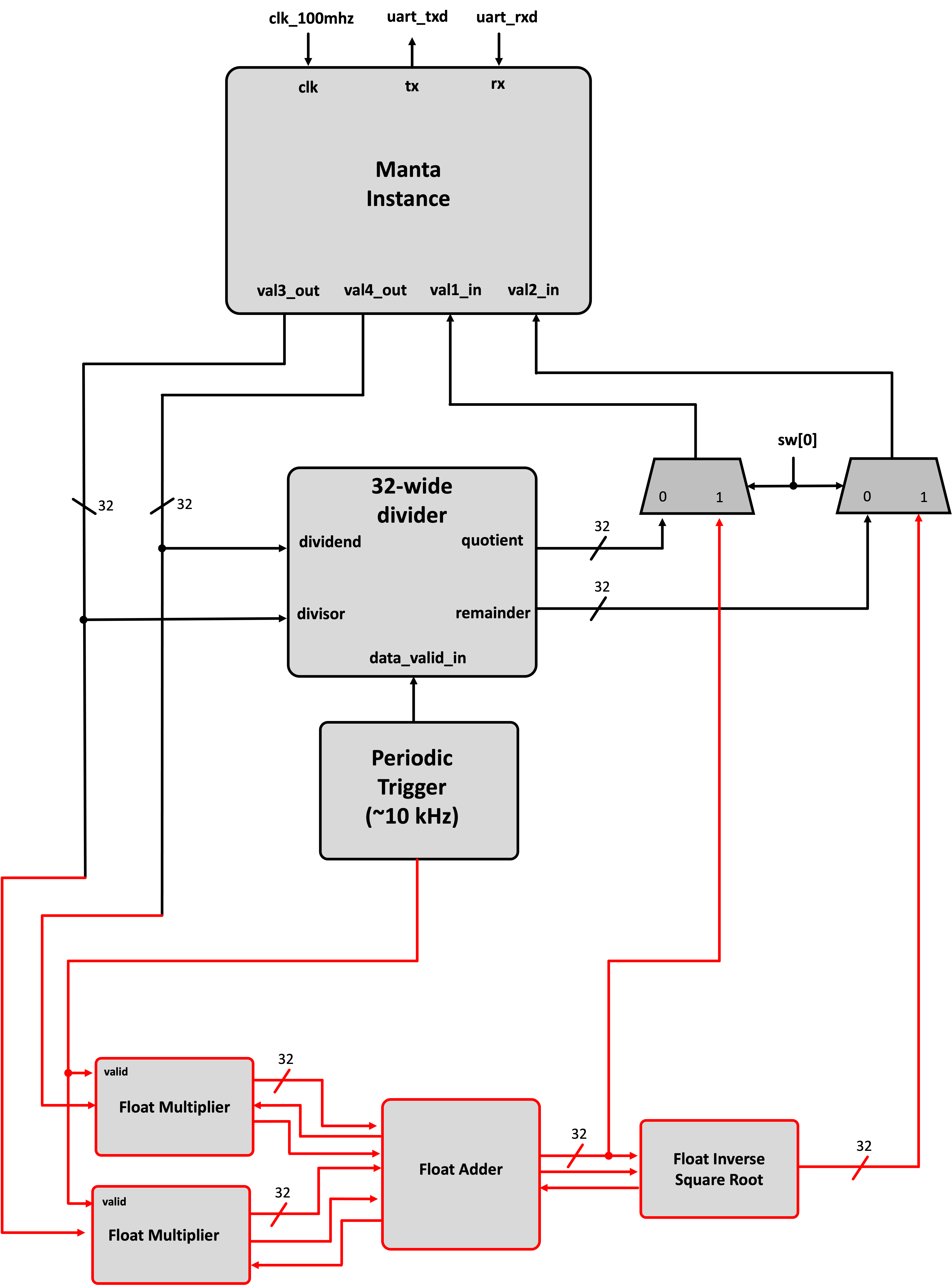
With this, now it is time to design. You can utilize instances of these IP modules just like any other module. We did this already in lecture 10 and now you need to do that. Create an AXI-streaming pipeline that does the math operation discussed above. Note we'd like to keep the integer pipeline still accessible, so set things up to route its results (or the floating pipeline's results) to the manta instance based on whether switch sw[0] is flipped or not.
Also pay special attention to the two signals we're grabbing. We want both the final result, but we also want the result from before the inverse square root. Make sure to capture/grab both the final and intermediate results by monitoring the valid signals generated along with these signals. If you just route these values to manta, depending on when we read the signals they may or may not be there!
When you are done run a build on your system. It will take a bit longer than usual since turning the IP into stuff takes a bit more time. That's ok.
Now how do you test this? We want to make sure that we can put floating point values into the FPGA and actually get the correct floating point results out. Start with your Python test script from the first part and modify it so that you are sending down the. You may try to just do something like:
m.lab8_io_core.val3_out.set(15.1)
...But that won't work. Manta will only take in integers for its setting values and will only return integers from gets. This is to ensure you're only placing unambigous binary values into the system. As a result, you need to figure out how to test your system with floating point values. There's many ways to do this, but one recommendation would be to dig into the struct library that Python has built-in. It lets pack and unpack the binary contents of different data types into different formats.
Generate a testing script similar to the one you had for integer division verification and verify at least five pairs of input floats and their corresponding outputs!
Ok this is done and working! Show staff and convince us that this is doing the floating point operation you designed. (compare to software-computer values)
Submit your Top level file below:
top_level.sv module here.